Environmental assessment of rammed earth construction systems: comparison between traditional and contemporary methods
Abstract
Numerical analysis has become a practical means of investigating nonlinear structural behavior, going beyond the scope of usual design simplifications. This paper presents a parametric investigation based on nonlinear finite element simulations of partially encased steel–concrete composite beams subjected to flexural loading. The numerical formulation accounts for concrete cracking, steel yielding, and the steel–concrete interaction through interface elements. The main interface parameters were calibrated by inverse analysis based on results from a four-point bending test, and the calibrated model was then validated against the experimental response. After validation, a systematic set of models was assessed to quantify the influence of steel profile symmetry, concrete strength, and the presence of reinforcement placed between the profile flanges. The results indicate that profile symmetry is the factor governing load-carrying capacity and the global response, while concrete strength becomes more influential when asymmetric profiles are adopted. The inclusion of reinforcement between the flanges provides a modest increase in ultimate capacity and does not significantly change the force–displacement response.
Keywords
Finite element analysis; Partially encased composite beam; Composite elements; Parametric study
Resumo
A análise numérica tem se consolidado como um caminho prático para investigar o comportamento estrutural não linear, indo além do alcance de simplificações usuais de projeto. Este artigo apresenta uma investigação paramétrica baseada em simulações não lineares por elementos finitos de vigas mistas aço–concreto parcialmente revestidas, submetidas à flexão. A formulação numérica contempla a fissuração do concreto, o escoamento do aço e a representação da interação aço–concreto por meio de interface. Os principais parâmetros da interface foram calibrados por análise reversa com base em resultados de um ensaio de flexão em quatro pontos, e o modelo calibrado foi então validado frente à resposta experimental. Após a validação, foi avaliado um conjunto sistemático de modelos para quantificar a influência da simetria do perfil metálico, da resistência do concreto e da presença de armadura disposta entre as mesas do perfil. Os resultados indicam que a simetria do perfil é o fator que governa a capacidade resistente e a resposta global, enquanto a resistência do concreto se torna mais influente quando se adotam perfis assimétricos. A inclusão de armadura entre as mesas proporciona um ganho modesto de capacidade última e não altera de forma significativa o comportamento das curvas força–deslocamento.
Palavras-chave
Método dos elementos finitos; Viga parcialmente revestida; Elementos mistos; Estudo paramétrico
1 Introduction
One type of the structural member in the composite steel concrete construction is the concrete encasing structural steel. Due to the encasement of steel columns or beams with concrete, the strength, stiffness and energy absorption capacity of composite members can greatly increase and it has been a common way to improve the ductility of concrete members in seismic areas, as mentioned in former studies (Moradian; Hassan, 2024; Zhou et al., 2026).
The method by which concrete connects to the steel profile is a crucial area of study for researchers in the field. Through the literature review (Yusuf et al., 2025; Kataoka; Spavier; El Debs, 2025), three primary types of connections were identified: stud bolts, web openings in the steel profile, and steel bars. The first method involves stud bolts welded to the steel profile to prevent differential displacement between the two materials. In steel profiles with web openings, the concrete slab sits between the steel flanges and is linked to the steel profile through these openings, enhancing longitudinal and vertical shear resistance. Lastly, steel bars are sometimes utilized as stirrups to provide shear resistance to the composite element.
The partially encased composite beam serves as a structural component within the composite slim floor system, a type of element that has been under study in Brazil since 1998, when the first paper was published (Queiroz et al., 1998). In subsequent research, stud bolts were consistently used as the connecting element, with analyses focusing on the influence of the shear connector position—whether in the web or flange—on the bending resistance of the composite beam. With the recognized advantages of the composite system and its increasing adoption in construction projects, research endeavors persist in addressing questions about its behavior. Experimental analyses on the behavior of partially encased composite beams were conducted by De Nardin and El Debs (2009) and by Cavalvanti and De Nardin (2011). These studies introduced parameterization to analyze the influence of the shear connector position on the beam's bending resistance.
Lacki et al. (2019) conducted an experimental and numerical investigation of steel–concrete composite beams with stud connectors. Their study evaluated the composite response in terms of slip and load-bearing capacity, following the serviceability assessment approach recommended by Eurocode 4 (CEN, 2004). Additionally, they examined the impact of the connector bend length on its load-bearing capacity and slip. Lima et al. (2022) explored the behavior and strength of orthogonal truss shear connectors for steel–concrete composite beams. They employed a nonlinear finite element model to simulate connector tests and validate the numerical model with experimental studies. Their research emphasized the effect of the connector bar diameter and concrete strength on the shear strength of the orthogonal truss connector.
Several studies on the behavior of partially encased composite beams are currently underway, focusing on steel profiles with openings in the web. This type of connection between steel profiles and concrete has been studied for many years, with notable previous works by Redwood and Poumbouras (1983) and Cho and Redwood (1992). Presently, this topic remains relevant, and experimental tests are being conducted to enhance the behavior of composite structures (Park; Kim; Yang, 2003; Ju; Chun; Kim, 2009; Chen; Gu; Li, 2011; Li et al., 2015; Li; Zhang; Zhou, 2020; Wu et al., 2023). With technological advancements, studies are also being conducted through numerical simulation, as it requires less time and financial support to perform research (Tsavdaridis; D’Mello; Huo, 2013; He; Yang, 2015; Kara, 2016; Li et al., 2020). Experimental and numerical studies complement each other, and based on the results of tests and simulations, theoretical studies have been developed to describe a calculation procedure for designing this type of composite structural member (Zhou, 2003; Wang et al., 2013; Ferreira; Martins; De Nardin, 2020).
Considering the third method, tests have highlighted the significance of reinforcing bars and the concrete between the flanges of composite beams for calculating the ultimate bending moment, ultimate shear force, and deflection (Kindmann; Bergmann, 1993). The contribution of this reinforcement is already stated in previous studies (Nakamura; Narita, 2003; Yuchen et al., 2016; Gao et al., 2024).
Despite the significant advances reported in the literature, a consistent and comparative evaluation of the combined influence of key parameters, such as steel profile geometry, concrete compressive strength, and the presence of reinforcement between the flanges, remains limited. Most existing studies have focused on specific aspects of composite behavior, often addressing these parameters in isolation, which makes it difficult to assess their relative importance within a unified framework.
This paper focuses on the numerical investigation of the mechanical behavior of partially encased composite beams with stud bolts welded to the web. In order to address the aforementioned aspects within a unified framework, a three-dimensional nonlinear finite element model is developed, incorporating material nonlinearities and the interaction between steel and concrete through interface elements.
The model is calibrated by inverse analysis based on experimental results from De Nardin and El Debs (2009) and subsequently validated to ensure its ability to reproduce the structural response. After validation, the numerical model is employed to perform a parametric analysis, including the evaluation of the influence of the steel profile cross-section, the compressive strength of the concrete encasement, and the presence of reinforcement between the flanges.
2 Experimental program
Results of partially encased composite beams were selected from the experimental program previously performed by De Nardin and El Debs (2009) for the purpose of verifying if the finite element model developed in the present study reproduces the experimental behavior.
2.1 Specimen description
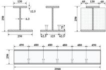
The specimen of the partially encased composite beam underwent a flexural test, and the experimental results were utilized in this study to validate the numerical model. The partially encased composite beam featured an asymmetric steel section with concrete filling between the flanges, measuring 2900 mm in length and 250 mm in height.
In order to provide composite action, shear studs were welded to the bottom flange of the asymmetric steel profile. These shear studs were 75 mm in length with a diameter of 19 mm and were spaced 480 mm apart, as depicted in Figure 1. The test was conducted at the Laboratory of the Structural Engineering Department (SET), University of São Paulo.
2.2 Test setup and instrumentation
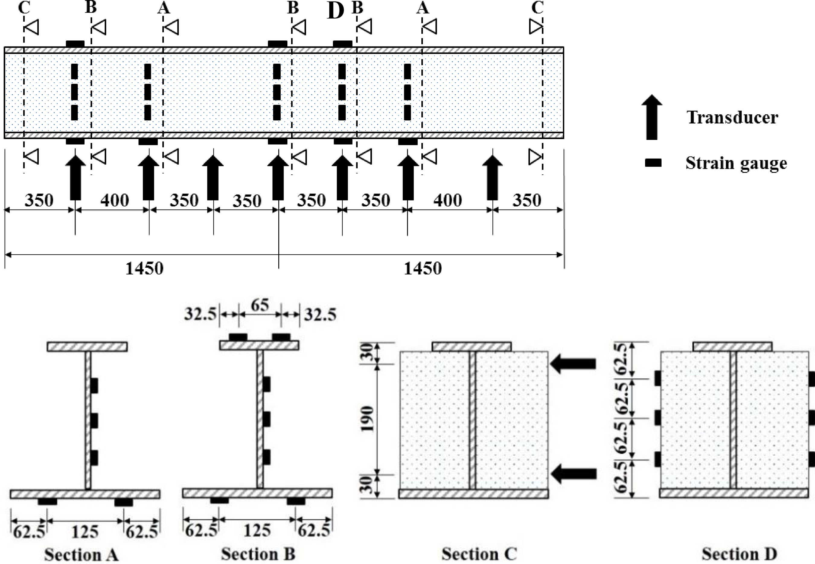
Displacement transducers were employed to measure the vertical displacement beneath the beam and the slip between the steel and concrete at the extremities. For the latter, four 20mm displacement transducers were positioned at both ends of the composite beam. Strains in both the asymmetric steel profile and concrete encasement were recorded using thirty-seven strain gauges, as illustrated in Figure 2.

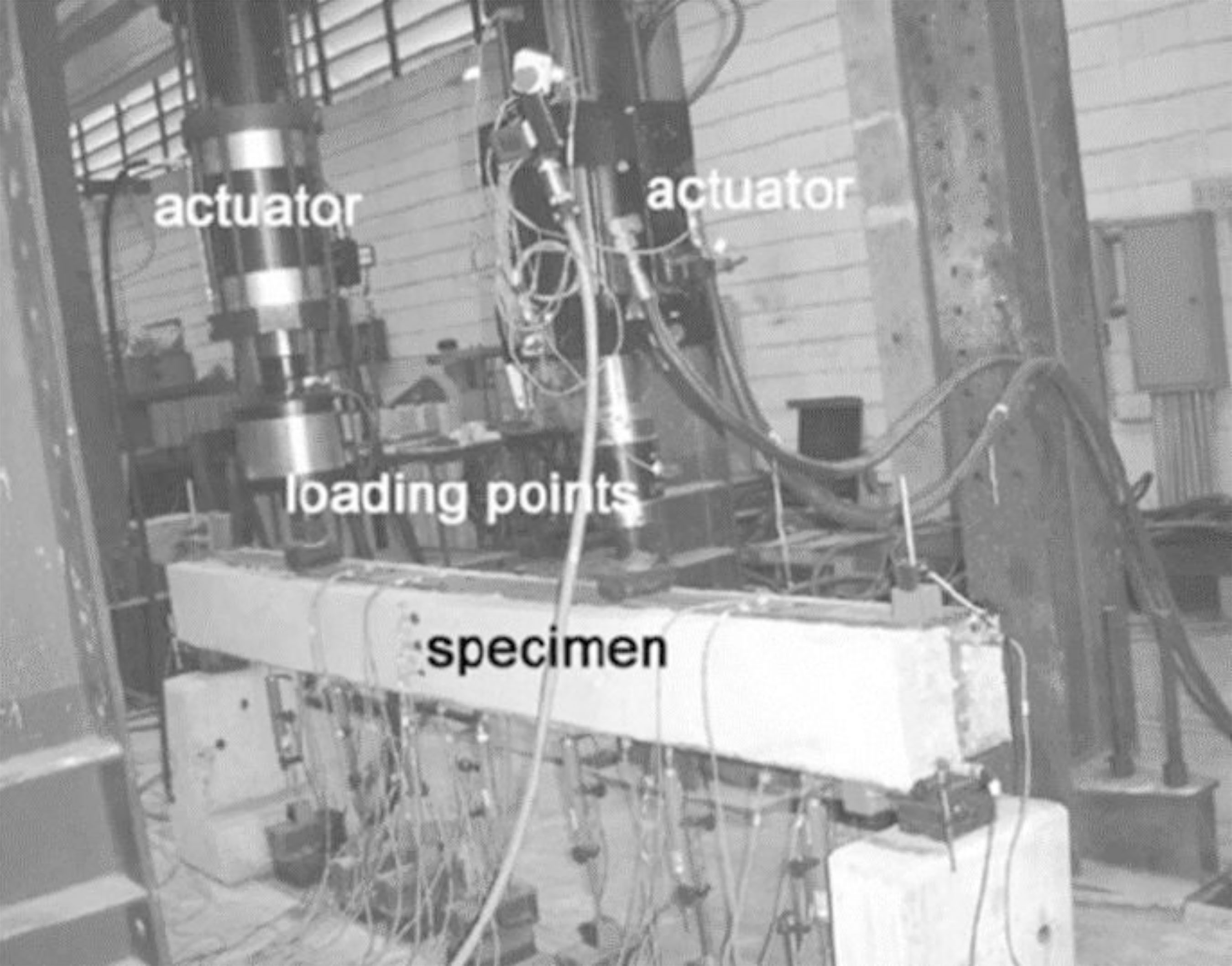
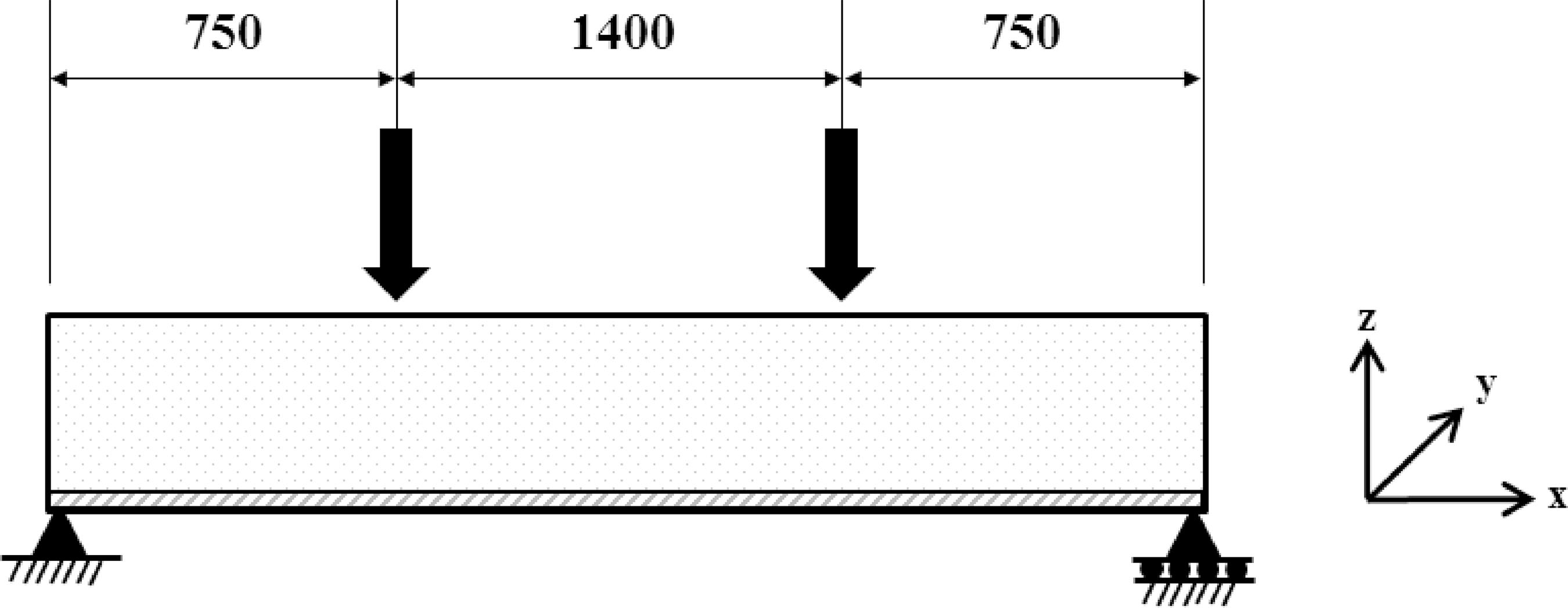
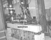
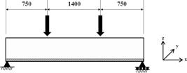
In the test setup, the partially encased composite beams were supported by rigid blocks, and two static loads were symmetrically applied using servo-controlled hydraulic jacks mounted on test rigs attached to the laboratory reaction frame, as depicted in Figure 3. These loads were applied monotonically under displacement control at a rate of 0.05 mm/s. The distance between the load points was 1400 mm.
2.3 Materials properties
The concrete used in the encasement of the partially encased composite beam was designed to have a compressive strength of 30 MPa. Twelve cylinders with a diameter of 100 mm were utilized for strength tests. The compressive (fc) and tensile (ft) strengths were measured as 3.57 and 0.27 kN/cm2, respectively. The longitudinal elasticity modulus of the concrete (Ec) was determined to be 3229 kN/cm2.
For the steel tensile test coupons, material was extracted from the webs and flanges of the beam. The average values of yield strength (fy) and ultimate strength (fu) were found to be 30.8 and 46.9 kN/cm2, respectively.
3 Finite element model
3.1 Geometry
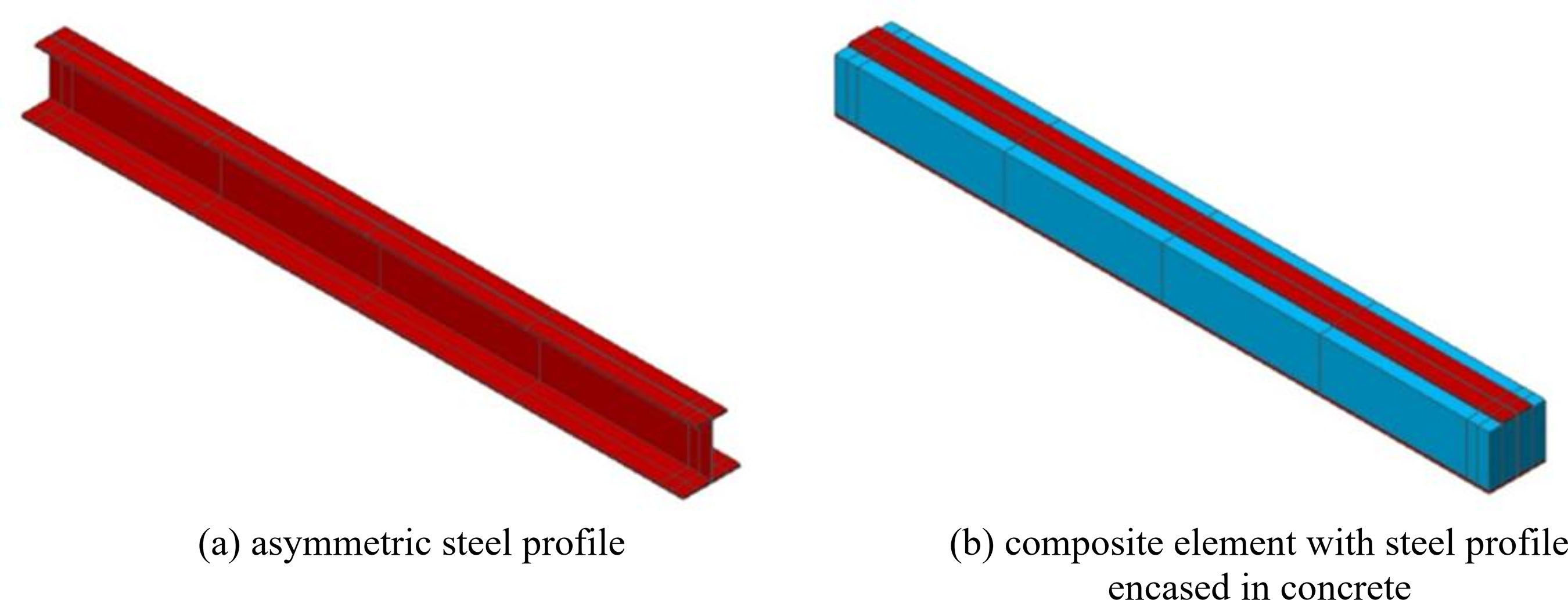
The finite element model was developed to predict the capacity and reproduce the behavior of a partially encased composite beam subjected to a flexural test. The numerical model was designed to include an asymmetric steel profile, concrete encasement, and the interface between steel and concrete. Figure 4(a) illustrates the asymmetric steel profile, whereas Figure 4(b) depicts the composite element, in which the steel profile is encased in concrete.
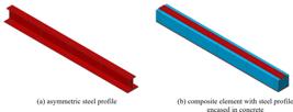
Geometry of the numerical model of partially encased composite beam: (a) asymmetric steel profile; (b) composite element with steel profile encased in concrete
The software Midas FX+ was utilized for constructing the geometry and for visualizing the results (both pre- and post-processing). The DIANA 10.0 software was employed for processing the numerical model using the finite element method (FEM).
3.2 Materials: properties and constitutive models
The mechanical properties input into the numerical model for the concrete and steel profile, such as compressive strength, tensile strength, Young modulus, and yielding stress, were derived from the values determined in the experimental program. As the fracture test of the concrete was not conducted, the determination of the tensile fracture energy relied on the provisions of the CEB Model Code 1990 (CEB, 1993), as described in Equation 1.
Where:
fcm = Average compressive strength; and
Gf0 = 0.03 for maximum aggregate diameter equal to 16 mm.
The compressive fracture energy was assumed to be fifty times the tensile fracture energy, following the recommendation of Feenstra and Borst (1993). The shear and normal stiffness of the steel–concrete interface were determined through a back-analysis procedure, in which the experimentally obtained mechanical properties of steel and concrete were kept unchanged, and only the interface stiffness parameters were adjusted until the numerical model reproduced the load–displacement response observed in the experimental tests. A value of 100 N/mm³ was selected as it provided the best agreement between numerical and experimental results.
During the calibration process, the sensitivity of the numerical response to variations in the interface stiffness was qualitatively assessed by analyzing different stiffness values. It was observed that this parameter mainly influences the initial stiffness of the load–displacement curve, while the ultimate load and overall structural behavior are only slightly affected. Lower interface stiffness values result in increased deformability and larger relative displacements, whereas higher values lead to a stiffer initial response.
Based on these observations, the adopted value was considered representative for accurately capturing the composite interaction within the scope of the present study. Table 1 summarizes the mechanical properties adopted in the numerical model, including those of the steel profile, concrete, interface, and the reinforcing steel bars considered in the parametric study.
The constitutive models for the materials are described as follows:
-
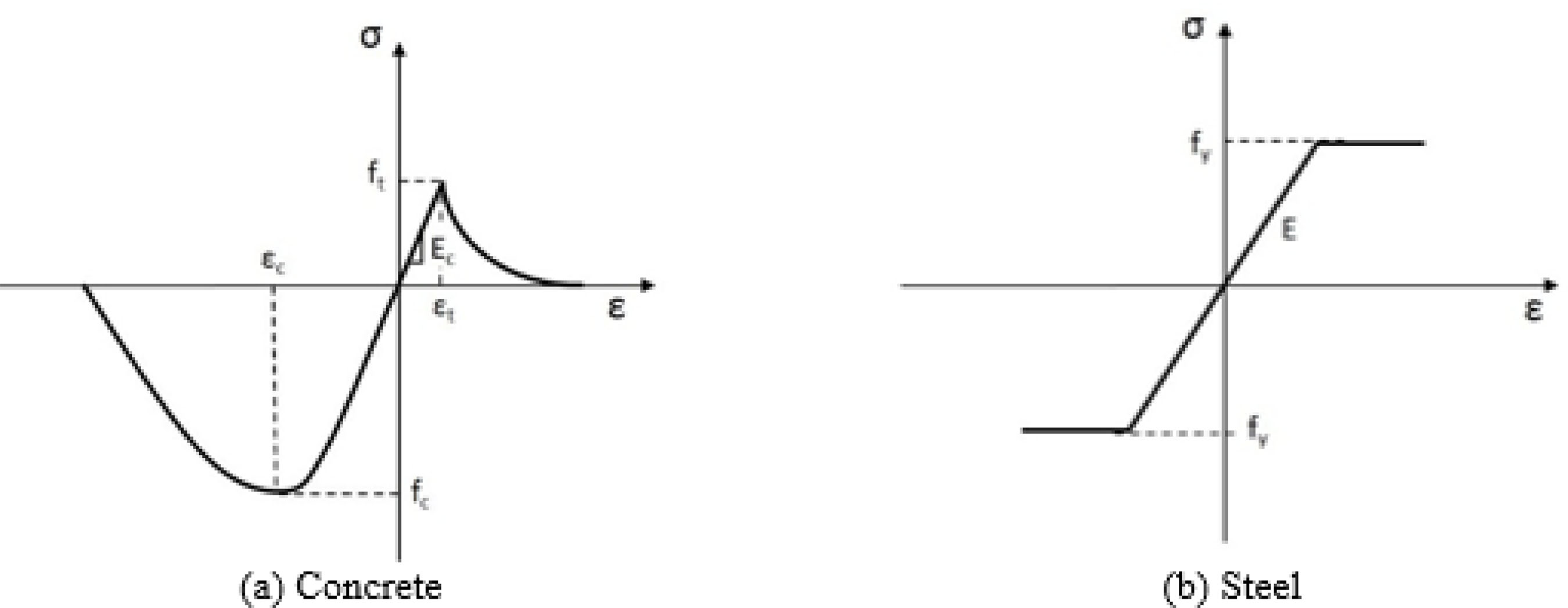
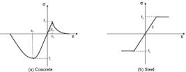
concrete: a constitutive model suitable for brittle or quasi-brittle materials was employed for the concrete. To characterize the distribution of cracks, the Total Strain model was utilized. This model can be represented by either the Rotating Crack Model or the Fixed Crack Model. In the numerical model developed for this study, the Fixed Crack Model was used. The tensile behavior of concrete was assumed to be brittle, while an ideal elastic-plastic model was utilized for compression, as illustrated in Figure 5(a);
-
steel profile: plasticity models such as Tresca and Von Mises are applicable to steel elements due to their ductile nature. The Von Mises model of maximum energy distortion was selected for the steel elements in this model, based on the assumption that the maximum energy accumulated in the material's distortion could not exceed the maximum distortion energy observed in a uniaxial tensile test of the same material. In essence, a Metal model was adopted with the Von Mises plasticity criterion and ideal plasticity without consideration of hardening or strain hardening. In the ideal plasticity model, also known as the perfectly plastic model, the material does not sustain loads beyond reaching the yield stress, as depicted in Figure 5(b); and
-
interface: interface elements are typically employed to analyze the contact between structural elements. In this study, structural interface elements were utilized. For the joints considered in the numerical model, the interface was represented by a constitutive model for cracking, with discrete cracking behavior. Table 2 shows the input properties of the materials constitutive models;
-
reinforcement steel bars: the steel bars, including bolts, slab reinforcement, and shear connectors, were modeled using the REINFORCE tool available in DIANA 10.0, which is specifically designed to represent embedded reinforcement. With this approach, the finite elements intersected by the REINFORCE elements are locally stiffened, thereby reproducing the mechanical contribution of the steel bars within the concrete matrix, in a manner consistent with the behavior of reinforced concrete structures.
3.3 Finite elements
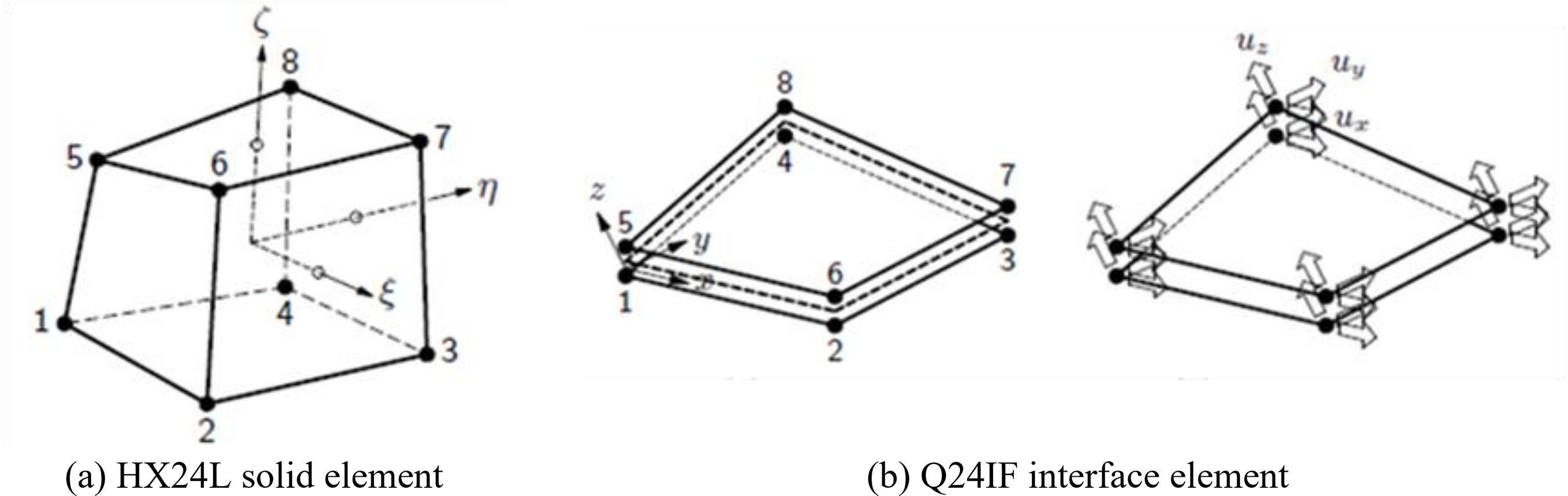
Two types of finite elements were employed to construct the mesh: three-dimensional solid continuum elements and interface elements. Solid 3D elements were used to represent the concrete filling and the steel profile, while interface elements were employed at the joint between steel and concrete. The solid element chosen was HX24L (Figure 6), featuring eight-node isoparametric elements with three degrees of freedom per node, based on linear interpolation and Gauss integration. The interface element used was Q24IF (Figure 6), which comprises 4 + 4 nodes with three degrees of freedom per node. Q24IF is designed as an interface element between two planes in a three-dimensional configuration with linear interpolation (Diana Finite Element Analysis, 2020).
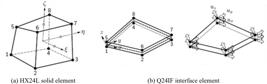
Finite elements used in the numerical models: (a) HX24L solid element; (b) Q24IF interface element (Diana Finite Element Analysis, 2020)
3.4 Mesh and boundary conditions
An appropriate finite element discretization was adopted to accurately represent the structural response while maintaining computational efficiency. The solid elements used in the analyses had characteristic dimensions of approximately 20 mm in all three spatial directions. This discretization was defined based on a balance between accuracy and computational cost, considering typical requirements for three-dimensional nonlinear analyses involving concrete cracking and steel plasticity.
Although a detailed mesh convergence study was not the main focus of this work, preliminary numerical checks indicated that further mesh refinement does not significantly affect the global structural response, particularly in terms of ultimate load. Therefore, the adopted discretization was considered adequate for the purposes of the present parametric investigation.
The beams were modeled as simply supported. Accordingly, the boundary conditions consisted of constraints on displacements in the x, y, and z directions at one end of the model, and constraints on displacements in the y and z directions at the opposite end, as illustrated in Figure 7.
3.5 Nonlinear solution strategy
The solution of the nonlinear system of equations was performed using an incremental-iterative procedure based on the secant method. This approach updates the stiffness relationship between successive iterations, contributing to numerical stability and reducing computational cost in nonlinear analyses involving material and interface nonlinearities.
The equilibrium equations were solved incrementally under displacement-controlled loading, in accordance with the experimental procedure. At each load increment, an iterative process was carried out until convergence was achieved. The convergence criteria were defined based on both force and displacement norms, ensuring that residual forces and displacement increments remained within prescribed tolerances.
The adoption of combined convergence criteria is particularly important in nonlinear analyses of composite structures, where multiple sources of nonlinearity are present, such as concrete cracking, steel yielding, and steel–concrete interface slip. These mechanisms may lead to stiffness degradation and localized responses, making it necessary to simultaneously control equilibrium and kinematic compatibility during the iterative solution process.
The adopted solution strategy proved to be robust for all numerical models analyzed, allowing stable convergence throughout the loading history, including near the ultimate load, where nonlinear effects become more pronounced.
4 Validation of the numerical model
The experimental results served as a reference to validate the numerical model. A comparison was conducted between various aspects of the behavior of the partially encased composite beam, including the ultimate load, vertical displacement, and strains.
4.1 Ultimate load and the behavior of the deflections
The main aspect that characterizes the behavior of the composite beam is the load versus displacement curve at mid-span. By calibrating the computational model to approximate the numerical and experimental load–displacement curves, it is possible to define the parameters governing the steel–concrete interaction, since the properties of the other materials were obtained from experimental characterization tests. The adopted interface parameters are presented in Table 1. This procedure is commonly referred to as back analysis.
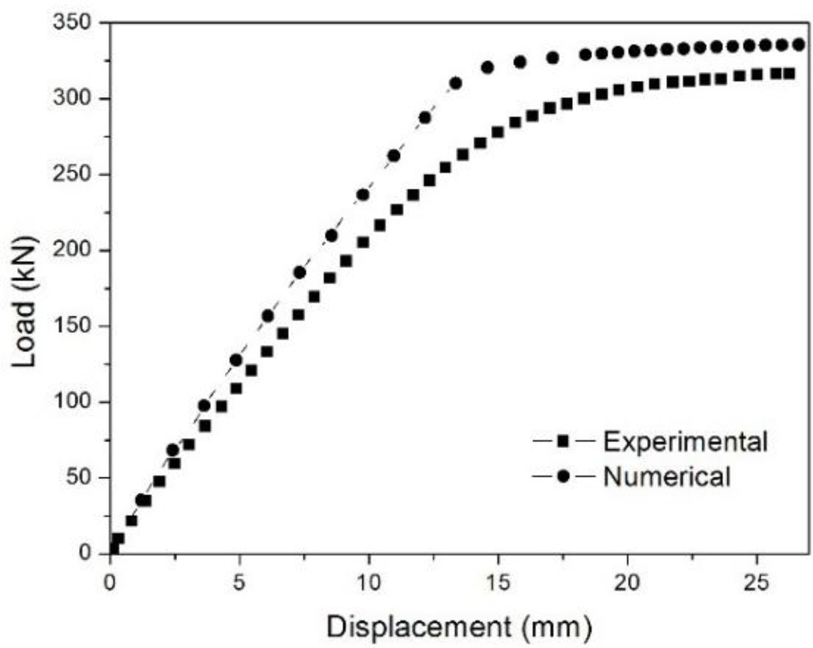
The comparison between experimental and numerical data revealed that the numerical model is stiffer than the experimental model, as depicted in Figure 8. However, the difference in stiffness is not significant and may be attributed to modeling assumptions adopted in the numerical analysis.
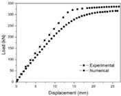
The higher stiffness observed in the numerical model compared to the experimental response can be attributed to the way the steel–concrete interaction was represented. In the present study, the stiffness associated with the shear connectors was incorporated into the interface elements, resulting in a continuous and equivalent representation of the connection between the materials.
Although this approach is suitable for reproducing the global structural response, it may lead to an overestimation of stiffness in the initial loading stages, since it does not explicitly represent local effects associated with the discrete behavior of the connectors, such as micro-slip and localized deformations.
In addition, the calibration of the interface parameters based on the global response tends to prioritize agreement at higher load levels, and may not accurately capture the initial deformability of the system. As a result, the numerical model exhibits a stiffer response in the early stages when compared to the experimental behavior.
Despite these simplifications, the overall agreement between numerical and experimental results remains satisfactory, particularly in terms of load-carrying capacity and global structural behavior.
Considering the ultimate load, the maximum load reached by the experimental model was 317.2 kN, while that of the numerical model was 336.8 kN. These results show satisfactory agreement, with a difference of approximately 6%. Therefore, it can be concluded that the numerical model adequately represents the global structural behavior and is suitable for use in parametric analyses.
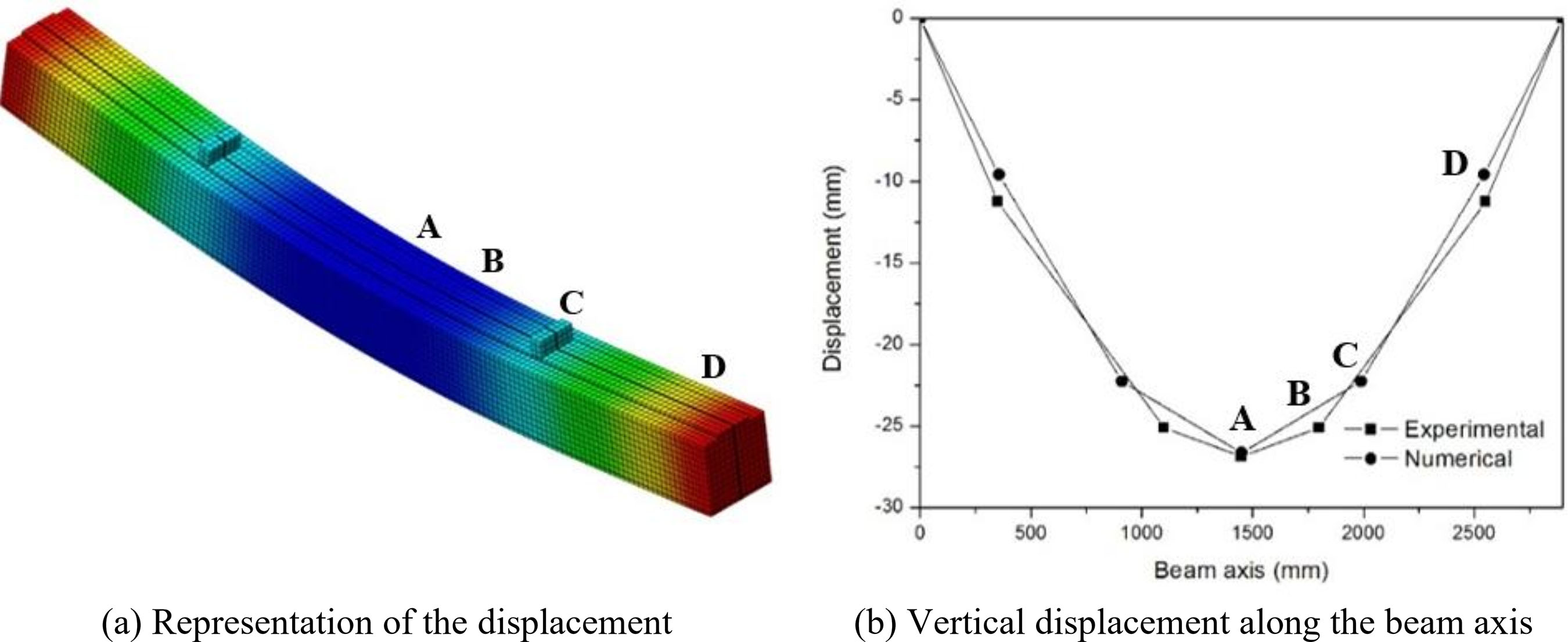
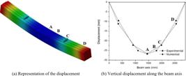
To illustrate the beam response, Figure 9(a) presents the numerical distribution of vertical displacements along the beam axis at the ultimate load, while Figure 9(b) compares the numerical and experimental displacement values at selected measurement points. The displacement readings were taken at four locations along the beam, corresponding to the displacement measurement points (transducers) indicated in Figure 2: point D, located 350 mm from the beam end; point C, located 750 mm from the beam end; point B, corresponding to the load application point; and point A, located at the mid-span of the beam. Based on the comparison at these locations, a satisfactory agreement between the numerical and experimental responses was observed.
4.2 Strain in the concrete encasement and steel profile
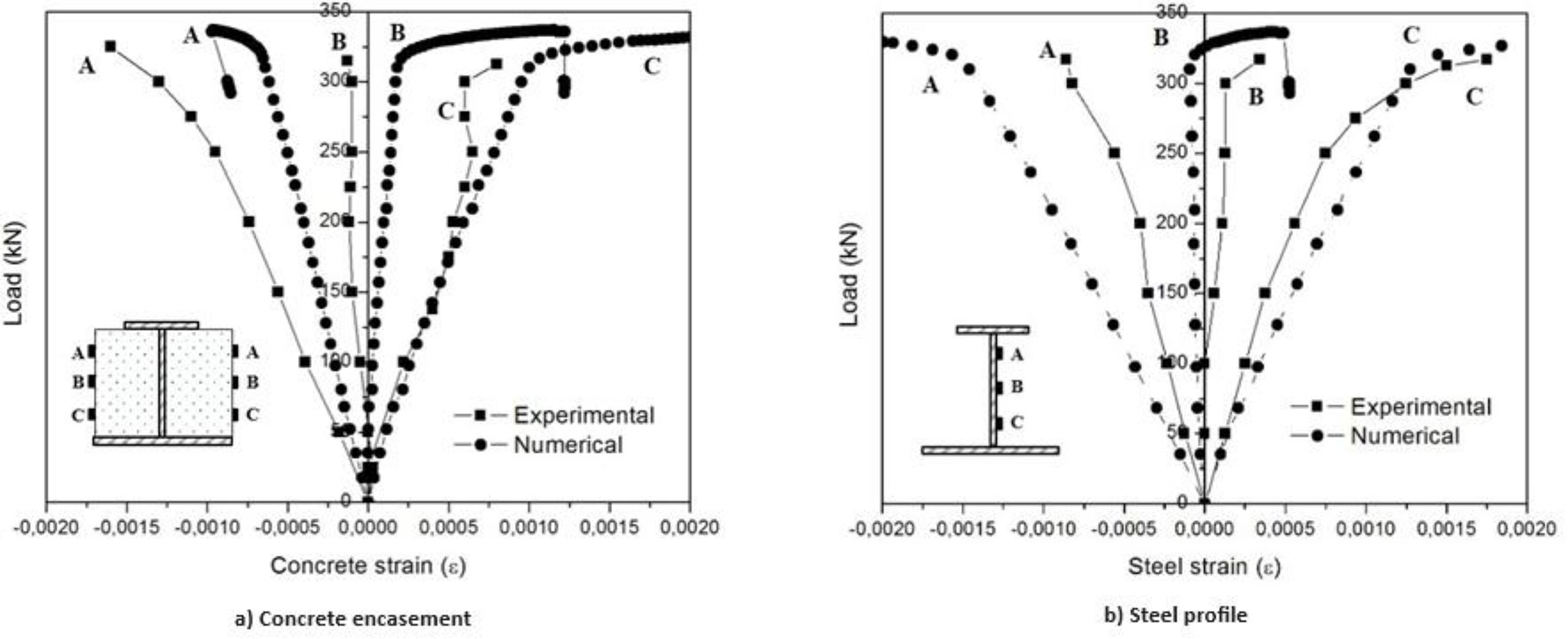
The strains in the concrete encasement were also compared between the numerical and experimental results. Figure 10(a) displays the strains in the concrete at the mid-span section for both the experimental and numerical models, showing a good correlation. The measurements were taken at three different heights of the beam to illustrate the position of the neutral axis. In both the experimental and numerical results, a similar behavior was observed: tensile strains were evident on the underside (indicated as letter C in Figure 10(a)), while compressive strains were observed on the top (indicated as letter A). At the midpoint of the beam, the strains approached zero, as indicated by letter B in Figure 10(a).

As expected, the numerical and experimental data also exhibited closer agreement when considering the strain in the steel profile. Figure 10(b) provides a comparison of the results, and based on the load versus strain steel curves, the findings are consistent. They indicate tensile strain at the bottom (indicated by letter C), compressive strain on the top (indicated by letter A), and neutral behavior in the middle of the cross-section (indicated by letter B).
5 Parametric study
Based on the ability of the proposed finite element model to reproduce the main experimental trends observed in the tested partially encased composite beam, a parametric analysis was carried out to further investigate its mechanical response. The influence of concrete compressive strength, steel profile cross-section, and the presence of reinforcement was evaluated.
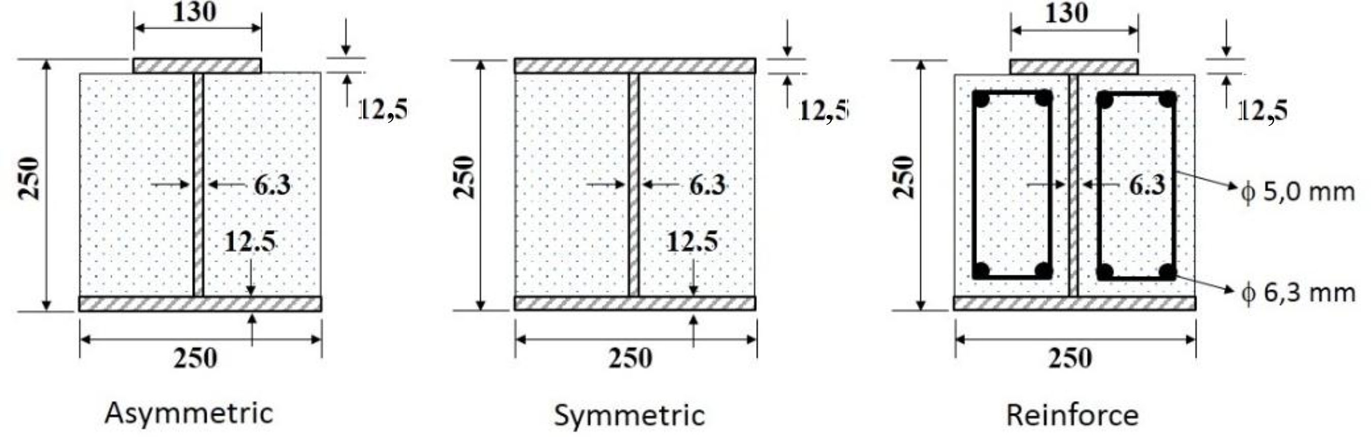
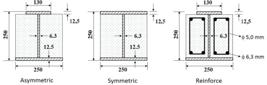
Concrete compressive strengths of 30, 50, 70, and 90 MPa were considered, combined with asymmetric and symmetric steel profile cross-sections (Table 3), as well as the inclusion of reinforcement between the flanges. The reinforcement layout consisted of four 6.3 mm diameter longitudinal bars on each side of the web and 5.0 mm diameter stirrups spaced at 100 mm, as illustrated in Figure 11. In total, twelve numerical models were analyzed in the parametric study, corresponding to four concrete strength levels for each cross-section configuration. In Table 3 presents the numerical models considered in the parametric study. In this notation, C30, C50, C70 and C90 denote concretes with characteristic compressive strength fck equal to 30, 50, 70 and 90 MPa, respectively.
The steel profiles maintained the same properties as those in the calibrated model. The concrete properties, such as tensile strength (fctm) and Young modulus (Eci), were calculated according to NBR 6118 (ABNT, 2023). Equations 2 and 3 were used for concretes with compressive strength between 20 and 50 MPa, while Equations 4 and 5 were employed for concretes with compressive strength between 55 and 90 MPa. The fracture energies, both tensile and compressive, were calculated based on the methodologies outlined in the CEB Model Code 1990 (1993) and by Feenstra and Borst (1993), respectively.
Where:
fck = characteristic concrete compressive strength;
Gf0 = 0.03 for maximum aggregate diameter equal to 16 mm; and
αE = coefficient that depends on the type of coarse aggregate used.
Table 4 presents the properties adopted for each cast in place concrete used in the parametric analysis.
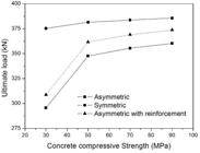
According to the parametric analysis, the concrete compressive strength had more significant influence on the behavior of composite beams with asymmetric steel profiles, whether with or without reinforcement. Conversely, for composite beams with symmetric steel profiles, the concrete compressive strength played a less important role.
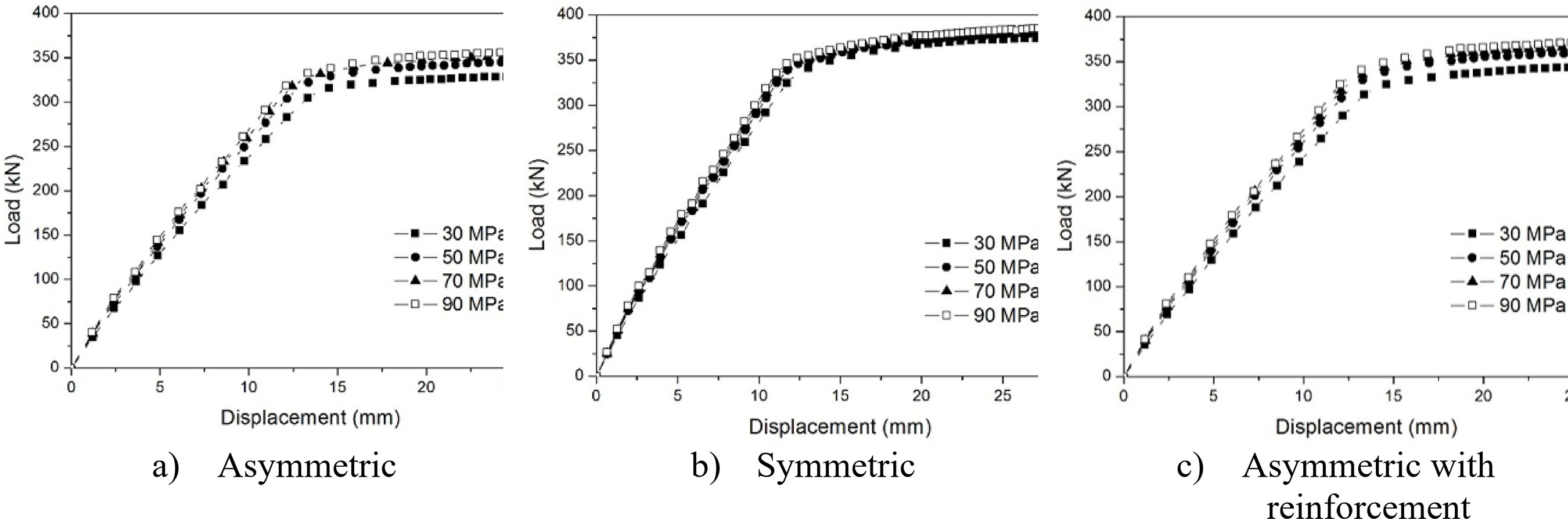
Considering the composite beams with asymmetric steel profiles, changing the concrete compressive strength from 30 MPa to 90 MPa led to a 22% increase in the ultimate load. In contrast, for symmetric profiles, the increase was only 2%. Table 5 provides a comparison, and Figure 12 illustrates the load versus displacement curves. The behavior of composite beams comprised of asymmetric profiles with reinforcement was similar to those without reinforcement, with a 21% increase in the ultimate load.
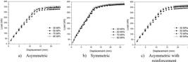
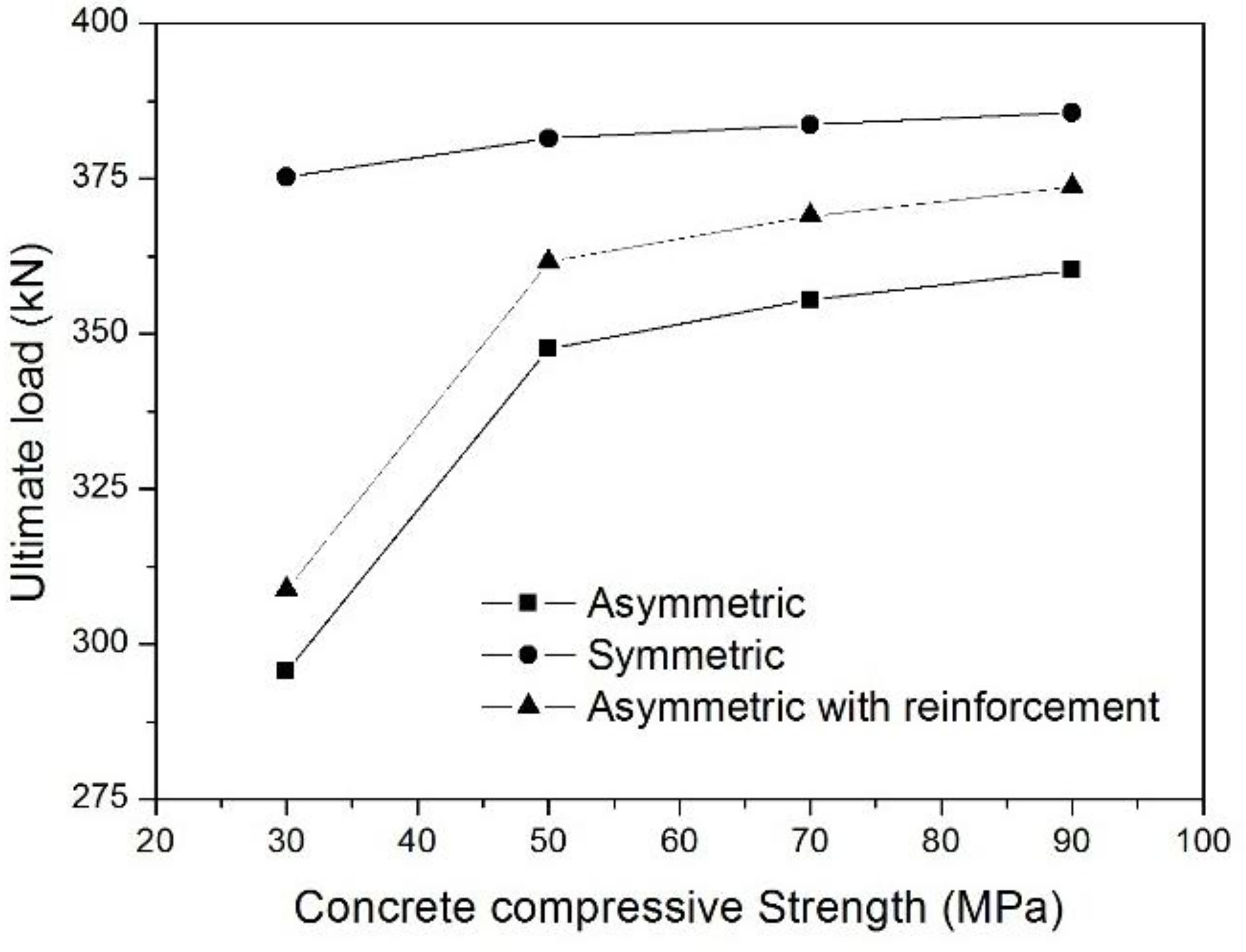
Figure 13 presents the ultimate load versus concrete compressive strength curves for three partially encased composite beams. Comparing the three behaviours, the composite beam with symmetric steel profile had better performance than the asymmetric, mainly for low concrete compressive strength (30 e 50 MPa). The ultimate load of symmetric steel profile was 27% higher than the asymmetric for concrete compressive strength of 30 MPa and an average of 8% for concretes with 50, 70 and 90 MPa.
The parametric study provided insight into the influence of concrete compressive strength, steel profile geometry, and the presence of reinforcement on the mechanical response of partially encased composite beams. The analysis focused on the global load–displacement behavior and ultimate load capacity, allowing a comparative assessment among the different numerical configurations.
For composite beams with asymmetric steel profiles, the results indicated a clear sensitivity to the concrete compressive strength. Increasing the concrete strength from 30 MPa to 90 MPa resulted in a noticeable increase in ultimate load, reflecting the significant contribution of the concrete encasement to load transfer and stress redistribution in this configuration. This behavior is associated with the asymmetric geometry, in which the concrete plays a more active structural role in resisting bending moments.
In contrast, composite beams with symmetric steel profiles exhibited a more stable response with respect to variations in concrete compressive strength. The numerical results showed only marginal increases in ultimate load as the concrete strength increased, indicating that, in this configuration, the steel profile governs the flexural capacity of the composite member. The more uniform stress distribution provided by the symmetric profile reduces the relative influence of the concrete encasement on the overall response.
The inclusion of reinforcement between the flanges led to a consistent, although modest, increase in ultimate load for the asymmetric composite beams. The reinforcement contributed to improving the confinement of the concrete and delaying localized cracking, which resulted in a small enhancement of the load-carrying capacity. For the configurations analysed, this enhancement corresponded to an average increase of approximately 4% in the ultimate load. However, the magnitude of this increase was limited, indicating that the reinforcement does not significantly alter the global mechanical response of the composite beam.
Comparisons among the load–displacement curves also indicated that changes in concrete strength and reinforcement primarily affected the ultimate capacity, while the overall shape of the curves remained similar. This observation suggests that the parametric variations influence the strength level rather than fundamentally modifying the deformation pattern or stiffness evolution of the composite system.
Overall, the parametric results highlight that the effectiveness of concrete strength and reinforcement depends strongly on the steel profile geometry. Asymmetric profiles benefit more from improvements in concrete properties and reinforcement, whereas symmetric profiles are less sensitive to these parameters. These findings provide a rational basis for selecting design strategies for partially encased composite beams according to the desired structural performance.
6 Conclusions
This study investigated the mechanical behavior of partially encased composite beams subjected to flexural loading through numerical simulations. A nonlinear three-dimensional finite element model was developed to represent the structural response of the composite beams. The adopted modeling strategy, including the representation of the steel–concrete interaction through interface elements and the calibration of interface parameters by inverse analysis, proved to be adequate for this purpose.
Comparisons between experimental and numerical results were carried out based on the load–displacement response, allowing the assessment of the model’s ability to reproduce the main experimental trends and to serve as a basis for parametric investigations within the adopted modeling assumptions. Based on the results obtained, the following conclusions can be drawn:
-
the comparison between numerical and experimental results showed satisfactory agreement in terms of global structural response, indicating that the finite element model was able to reproduce key aspects of the experimental behavior and is suitable for comparative parametric analyses;
-
the use of interface elements, instead of explicitly modeling shear connectors as solid elements, provided a simplified and effective approach for representing the composite action between steel and concrete within the scope of the present study;
-
partially encased composite beams with symmetric steel profiles exhibited higher ultimate load capacity compared to beams with asymmetric profiles and narrower top flanges, indicating a stronger contribution of steel profile geometry to flexural resistance in this configuration; and
-
the inclusion of reinforcement in the concrete encasement led to a consistent but limited increase in the ultimate load of the composite beams. As indicated by the parametric analysis, the average increase in load-bearing capacity was approximately 4%, suggesting that, for the configurations investigated, the reinforcement does not significantly modify the global mechanical response. Consequently, the economic viability of incorporating reinforcement should be further assessed, considering potential benefits beyond ultimate load capacity.
Overall, the results contribute to a more consistent understanding of the structural behavior of partially encased composite beams, particularly regarding the influence of the analyzed parameters, and support the use of the proposed numerical model in parametric and design-oriented analyses.
-
KATAOKA, M. N.; DE NARDIN, S. Structural behavior of partially encased composite beams: a numerical approach. Ambiente Construído, Porto Alegre, v. 26, e153505, jan./dez. 2026. ISSN 1678-8621 Associação Nacional de Tecnologia do Ambiente Construído. http://dx.doi.org/10.1590/s1678-86212026000101006
-
Declaration of Generative AI and AI-Assisted Technologies in the Writing Process
During the preparation of this work, the authors used ChatGPT in order to improve the language and readability of the manuscript. After using this tool, the authors reviewed and edited the content as needed and take full responsibility for the content of the publication.
-
Financial Support
None.
Data Availability Statement
All data generated or analyzed during this study are included in this published article.
Referências
- ASSOCIAÇÃO BRASILEIRA DE NORMAS TÉCNICAS. NBR 6118: projeto de estruturas de concreto. Rio de Janeiro, 2023.
- CAVALCANTI, L.; DE NARDIN, S. Análise experimental e comparativa da contribuição da armadura para a capacidade resistente de vigas parcialmente revestidas. Cadernos de Engenharia de Estruturas, v. 13, p. 99–114, 2011.
- CHEN, T.; GU, X.; LI, H. Behavior of steel-concrete composite cantilever beams with web openings under negative moment. International Journal of Steel Structures, v. 11, n. 1, p. 39–49, 2011.
- CHO, S. H.; REDWOOD, R. G. Slab behavior in composite beams at openings, II: tests and verification. Journal of Structural Engineering, v. 118, n. 9, p. 2304–2322, 1992.
- COMITÉ EURO-INTERNATIONAL DU BÉTON. CEB-FIP Model Code 1990: design code. London: Thomas Telford Services Ltd., 1993.
- COMITÉ EUROPÉEN DE NORMALISATION. EN 1994-1-1: Eurocode 4: design of composite steel and concrete structures: part 1-1: general rules and rules for buildings. Bruxelas, 2004.
- DE NARDIN, S.; EL DEBS, A. L. H. C. Study of partially encased composite beams with innovative position of stud bolts. Journal of Constructional Steel Research, v. 65, n. 2, p. 342–350, 2009.
- DIANA FINITE ELEMENT ANALYSIS. User manual Delft: TNO DIANA, 2020.
- FEENSTRA, P. H.; BORST, R. Aspects of robust computational modeling for plain and reinforced concrete. Heron, v. 38, n. 4, p. 3–76, 1993.
- FERREIRA, F. P. V.; MARTINS, C. H.; DE NARDIN, S. Advances in composite beams with web openings and composite cellular beams. Journal of Constructional Steel Research, v. 172, p. 106182, 2020.
- GAO, X. et al Flexural behaviors of a novel precast hollow UHPC composite beam reinforced with inverted T-shaped steel: experimental investigation and theoretical analysis. Journal of Building Engineering, v. 86, p. 108893, 2024.
- KARA, I. F. Flexural performance of FRP-reinforced concrete encased steel composite beams. Structural Engineering and Mechanics, v. 59, n. 4, p. 775–793, 2016.
- KATAOKA, M. N.; SPAVIER, P. T. S.; EL DEBS, A. L. H. C. Análise do comportamento estrutural de vigas mistas de aço e concreto: experimentação e dimensionamento. Ambiente Construído, Porto Alegre, v. 25, e142056, jan./dez. 2025.
- KINDMANN, R.; BERGMANN, R. J. Effect of reinforced concrete between the flanges of the steel profile of partially encased composite beams. Journal of Constructional Steel Research, v. 27, p. 107–122, 1993.
- LACKI, P. et al. Numerical and experimental tests of steel-concrete composite beam with the connector made of top-hat profile. Composite Structures, v. 211, p. 244–253, 2019.
- LI, L. et al. Behavior of continuous steel-concrete composite beams with web openings. International Journal of Steel Structures, v. 15, n. 4, p. 989–997, 2015.
- LI, L.; ZHANG, H.; ZHOU, D. Experimental study of high-strength bolt connected composite beams with web openings. Iranian Journal of Science and Technology, Transactions of Civil Engineering, v. 45, p. 1–10, 2020.
- LIMA, J. M. et al. Study of the behavior and resistance of right-angle truss shear connector for composite steel concrete beams. Engineering Structures, v. 253, p. 113778, 2022.
- MORADIAN, M.; HASSAN, M. The seismic behavior of rectangular concrete-encased steel bridge piers: a review. Applied Sciences, v. 14, n. 15, p. 6627, 2024.
- NAKAMURA, S.; NARITA, N. Bending and shear strengths of partially encased composite I-girders. Journal of Constructional Steel Research, v. 59, n. 12, p. 1435–1453, 2003.
- PARK, J. W.; KIM, C. H.; YANG, S. C. Ultimate strength of ribbed slab composite beams with web openings. Journal of Structural Engineering, v. 129, n. 6, p. 810–817, 2003.
- QUEIROZ, G. et al A new type of slim floor. Journal of Constructional Steel Research, v. 46, n. 1–3, p. 213–214, 1998.
- REDWOOD, R. G.; POUMBOURAS, G. Tests of composite beams with web holes. Canadian Journal of Civil Engineering, v. 10, n. 4, p. 713–721, 1983.
- TSAVDARIDIS, K. D.; D’MELLO, C.; HUO, B. Y. Experimental and computational study of the vertical shear behaviour of partially encased perforated steel beams. Engineering Structures, v. 56, p. 805–822, 2013.
- WANG, P. et al. Theoretical study on ultimate bearing capacity of composite beams with reinforced web opening. Engineering Mechanics, v. 30, n. 5, p. 138–146, 2013.
- WU, H. et al. Mechanical properties of composite beams with web openings under negative bending moments. Structures, v. 58, p. 105394, 2023.
- YUCHEN, J. et al. Experimental study and theoretical analysis of partially encased continuous composite beams. Journal of Constructional Steel Research, v. 117, p. 152–160, 2016.
- YUSUF, Y. et al. Strengthening techniques for steel–concrete composite beams: a comprehensive review. Eng, v. 6, p. 307, 2025.
- ZHOU, D. A method for calculation of composite beams with web openings: part 1. Stahlbau, v. 72, n. 9, p. 626–634, 2003.
- ZHOU, W. et al. Mechanical properties of L-section thin concrete encased steel columns under low-cycle loading. Journal of Building Engineering, v. 118, p. 115012, 2026.
Edited by
-
Editor-in-chief:
Marcelo Henrique Farias de Medeiros