Water–sediment separation experiment and numerical simulation in different gill-piece spacings of the gill-piece separation device
ABSTRACT
Filters facilitate the removal of sticky sediments and prevent clogging of drip lines and emitters, thereby sustaining stable micro-irrigation system operation. In this study, physical model experiments were carried out at first. In the experiment, utilizing the shallow layer sediment theory and the principles of settling characteristics of viscous particles, the influence of different gill-piece spacing on water–sediment separation efficiency was analyzed and investigated under realistic working conditions. Furthermore, numerical simulations were performed using the mixture model and RNG k – ɛ models within the CFX software to supplement and verify the experimental results. Finally, the projection pursuit regression method is used for verification. Through the numerical simulations, the water–sediment two-phase flow field and volume concentration of sediment were studied, the influence of gill-pieces and different gill-piece spacing on the water–sediment separation efficiency of the gill-piece separation device (GPSD) was investigated, and the optimal gill-piece spacing of the GPSD was further explored. The results showed that GPSDs performed better than ordinary tubes in water–sediment separation. There was no significant difference in the water–sediment separation effect when the gill-piece spacing was less than 50mm. By taking both the water–sediment separation efficiency and economic benefits into consideration in practical engineering, the optimal gill-piece spacing was determined to be 50mm. Compared to GPSDs with gill-piece spacings of 80 and 110 mm, the water–sediment separation efficiency of the GPSD with a gill-piece spacing of 50 mm was 1.21–1.42 and 1.35–1.77 times higher, reaching a peak efficiency of 35.41%. The GPSD filter is small in size, simple in structure, and highly cost effective.
Keywords:
water–sediment separation efficiency; mechanics of sediment movement; numerical simulation; gill-piece separation device; ordinary tube; gill-piece spacing
RESUMO
Filtros facilitam a remoção de sedimentos pegajosos e evitam o entupimento de linhas de gotejamento e emissores, mantendo assim uma operação estável do sistema de microirrigação. Neste estudo, foram realizados, primeiramente, experimentos com modelos físicos. No experimento, utilizando a teoria de sedimentos de camada rasa e os princípios das características de assentamento de partículas viscosas, foi analisada e investigada a influência de diferentes espaçamentos entre lamelas na eficiência de separação água-sedimentos sob condições de trabalho realistas. Além disso, foram realizadas simulações numéricas utilizando o modelo de mistura e os modelos RNG no software CFX para complementar e verificar os resultados experimentais. Finalmente, foi utilizado o método de regressão de projeção e perseguição para verificação. Por meio das simulações numéricas, foram estudados o campo de fluxo bifásico água-sedimento e a concentração volumétrica de sedimentos, foi investigada a influência das lamelas e de diferentes espaçamentos entre lamelas na eficiência de separação água-sedimentos do dispositivo de separação por lamelas (GPSD), e foi ainda mais explorado o melhor espaçamento entre lamelas do GPSD. Os resultados mostraram que os GPSDs tiveram melhor desempenho que os tubos comuns na separação água-sedimentos. Não havia diferença significativa no efeito de separação água-sedimentos quando o espaçamento entre lamelas era menor que 50 mm. Levando-se em conta tanto a eficiência de separação água-sedimentos quanto os benefícios econômicos na engenharia prática, o melhor espaçamento entre lamelas foi determinado como 50 mm. Comparado com GPSDs com espaçamentos entre lamelas de 80 e 110 mm, a eficiência de separação água-sedimentos do GPSD com um espaçamento entre lamelas de 50 mm foi 1,21-1,42 e 1,35-1,77 vezes maior, atingindo uma eficiência máxima de 35,41%. O filtro GPSD é pequeno em tamanho, simples em estrutura e altamente econômico.
Palavras-chave:
eficiência de separação água-sedimentos; mecânica do movimento de sedimentos; simulação numérica; dispositivo de separação por lamelas; tubo comum; espaçamento entre lamelas
INTRODUCTION
The northwestern areas in China are situated in the center of the Eurasian continent that is far away from the sea, featuring little precipitation and a strong evaporation effect. In these regions, over 90% of the total water consumption is used for agricultural irrigation, and there are problems of agricultural water shortage and low use efficiency of water (Zhang; Wei; Mao, 2023). To conserve water resources and enhance irrigation efficiency, various water-saving techniques like micro-irrigation, spray, bubbler, drip, and low-pressure irrigation are commonly employed. These methods minimize water wastage and optimize its use in agriculture (Sharafati et al., 2020; Wang et al., 2023; Younes et al., 2023; Li et al., 2024). However, when water-saving irrigation devices are used for irrigation, most drip lines and emitters in micro-irrigation systems are prone to clogging (An et al., 2023), especially in Xinjiang where the annual precipitation is less than a quarter of the national average (Zhai et al., 2021). The reason is that the river water in this region contains a large amount of sediment with a small particle size. To solve this problem, the river water is first purified in a settler installed with one or multiple sets of filters before it is delivered through drip lines and emitters to meet the needs of water in crop growth.
There are many domestic and foreign studies on inclined plate settlers, which show advantages in the initial treatment of sediment. Wang Yilin used the CFD software to determine the structural parameters of the modified inclined plate settler in the optimal operating condition (Wang, 2022). Wang Wenxin et al. (Shi et al., 2022) designed two new types of two-story horizontal settlers with an inclined plate structure. Hui, Zheng, and Yan (2021) discussed different sludge reflux and settling characteristics using high-efficiency inclined plate settlers. Iyer and James (2023) summarized the application status of sedimentation tank design and analysis and introduced the main factors affecting its hydraulic dynamics.
Many researchers have also studied filters and made some achievements. Sand filters are a medium filter with a strong capacity to filter pollutants and can supply water constantly (Kumar, 2023). Disc filters have the merits of a long filtration cycle, stable effluent quality, low filtrate loss, etc. (Xu et al., 2023) Screen filters perform well in removing inorganic impurities (e.g., sand, gravels, and scale) from water (Indah et al., 2023). Centrifugal filters rely heavily on both gravity and centrifugal force to eliminate solid particles that are denser than water, effectively purifying the water for various applications (Hou et al., 2022). Laminated filters are often used in secondary filters or filter systems for removing organic impurities from water with relatively good quality (Kasaraneni; Anaya; Taliani, 2024). In addition, the filtration mechanism and performance of different types of filters have also been studied (Puig-Bargués; Barragán; de Cartagena, 2005; Duran-Ros et al., 2009; Bové et al., 2015; Wen-Yong et al., 2015). Both physical model experiments and numerical simulations were utilized to investigate the filtration capabilities and head loss characteristics of diverse filter systems. The findings from these analyses deepened our comprehension of the intricate filtration process and internal flow dynamics within the filters (Yurdem; Demir; Degirmencioglu, 2008; Duran-Ros et al., 2010).
However, settlers used for settling sticky sediment in water for agricultural irrigation have the demerits of a large floor area and a long settling time (Zong et al., 2017). Moreover, currently available filters have the problems of easy clogging, frequent rinsing, and high equipment costs when used to process river water with high sediment content (SC). Adding inorganic salts and organic flocculants is sometime a feasible method of treating water with high SC, but it also has many shortcomings, such as the need for high doses, harm to human health, and environmental pollution (Zahrim; Tizaoui; Hilal, 2011). To address these problems, Qiu Xiuyun et al. created a new type of water–sediment separation device, namely, gill-piece separation device (GPSD), which is effective in separating water from sediment, economical and practical, covering a small area (Qiu et al., 2007). Currently, experts and researchers have extensively explored the Global Positioning System Drift (G-P-S-D) phenomenon, in both static and flowing water conditions, utilizing both experimental and numerical simulation methodologies. Yuecheng Yan et al. (2011); Zhu and Qiu (2009); Zhu, Qiu, and Sun (2009); Zhu (2009); Zhu, Qiu, and Yan (2009) investigated the vertical and horizontal density currents in the GPSD and optimized its structure preliminarily. The research revealed that the GPSD surpassed conventional tubes in its ability to swiftly separate water and sediment. This enhanced performance stemmed from the gill-pieces disrupting the rigid sediment structure formed during settling, which facilitated a more efficient separation process.
Tao Hongfei (Tao et al., 2013a; Tao et al., 2013c; Tao et al., 2014; Tao et al., 2015) made physical tests to gain an in-depth understanding of the structural and other characteristics of the GPSD in static water in conditions of different SC, gill-piece spacings, and gill-piece inclinations. It was found that when the sediment concentration was 10~80 in static water, the settling speed of sediment in the GPSD was faster, and the water–sediment separation effect was better. Moreover, the device achieved high water–sediment separation performance when the gill-pieces inclined at 60°along the length direction and 45°along the width direction. Thus, the optimal angles of inclinations along the length and width directions are 60°and 45°, respectively. According to the numerical simulations of the velocity and concentration fields of the GPSD in static water, the flow field distribution pattern of the device in static water conformed to a laminar flow model. The numerical simulation results revealed the mechanism of accelerated separation of water and sediment by the GPSD and theoretically verified the rationality of its structural parameters. Zhang Jiling (Zhang et al., 2019) analyzed the effect of the inlet flow rate on the water–sediment separation efficiency of the GPSD in flowing water conditions. In this study, the water–sediment separation pattern in flowing water conditions was unveiled, and the integrated suspension GPSD was proposed.
To facilitate the efficient use of the GPSD in practice, physical model experiments and numerical simulations were conducted based on the abovementioned research results in static water conditions in this paper. The comparative analysis and mathematical models (mixture and RNG) were used to further explore the influence of different gill-piece spacings on the water–sediment separation efficiency of the GPSD in flowing water environments and the interior flow field distribution pattern. The results are expected to provide a theoretical foundation and technical support for the practical application of the GPSD in agricultural irrigation in the future.
METHOD
Physical experiment
Device
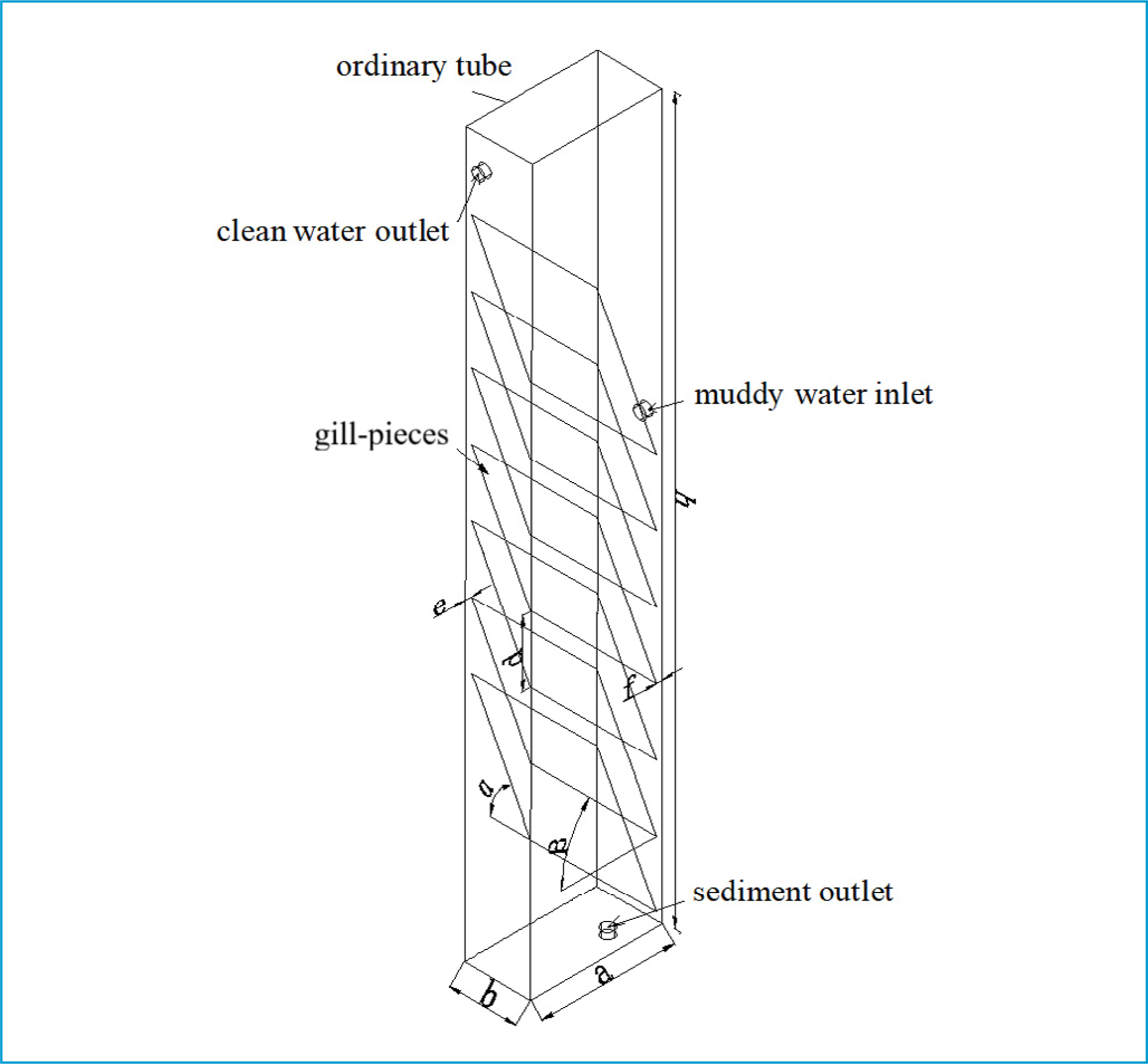
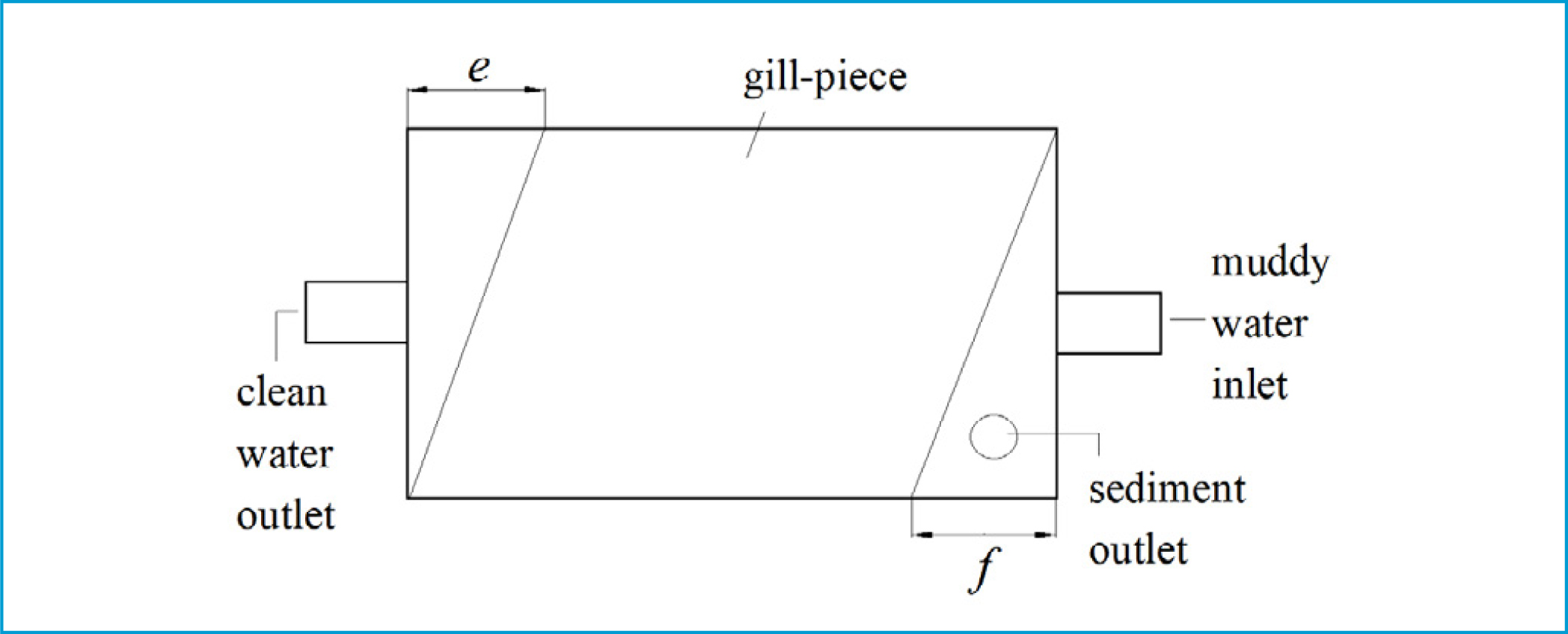
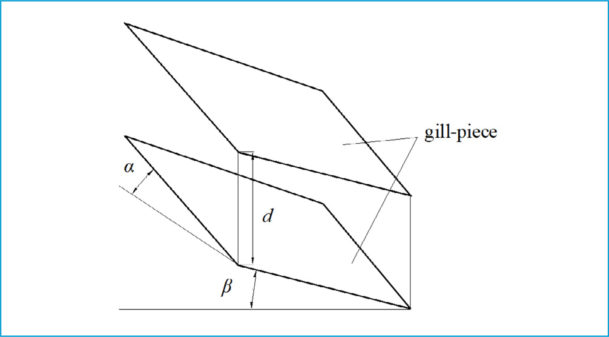
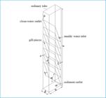
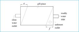
Figures 1, 2, and 3 illustrate the overall architecture of the GPSD, its aerial perspective, and a magnified view, respectively, of a segment of the gill-pieces. The device is made up of ordinary pipes and gill-pieces, measuring a×b×h=200 mm×100 mm ×1000 mm. The gill-pieces form inclinations of α=60° and β=45° with the side walls of the ordinary pipe in the length and width directions, respectively. Meanwhile, both side walls in the width direction are equipped with a triangular sediment descending channel and a clean water ascending channel. Their maximum widths are f=10mm and e=10mm, respectively. Both channels have a diameter of 20mm. The clear water outlet and the muddy water inlet are 950mm and 760mm from the bottom of the GPSD, respectively. The top of the device is open, and the bottom has a sediment discharge channel with a diameter of 2.5mm.
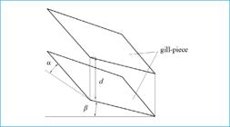
According to the results of settling tests of the GPSD in static water conditions, the gill-piece spacing had a large impact on water–sediment separation when it changed from 30 to 150mm (Tao, 2014). Therefore, five GPSDs with gill-piece spacings of 30, 40, 50, 80, and 110mm and an ordinary tube of the same size and the same material (without gill-pieces) were prepared. Comparison experiments were conducted in flowing water conditions.
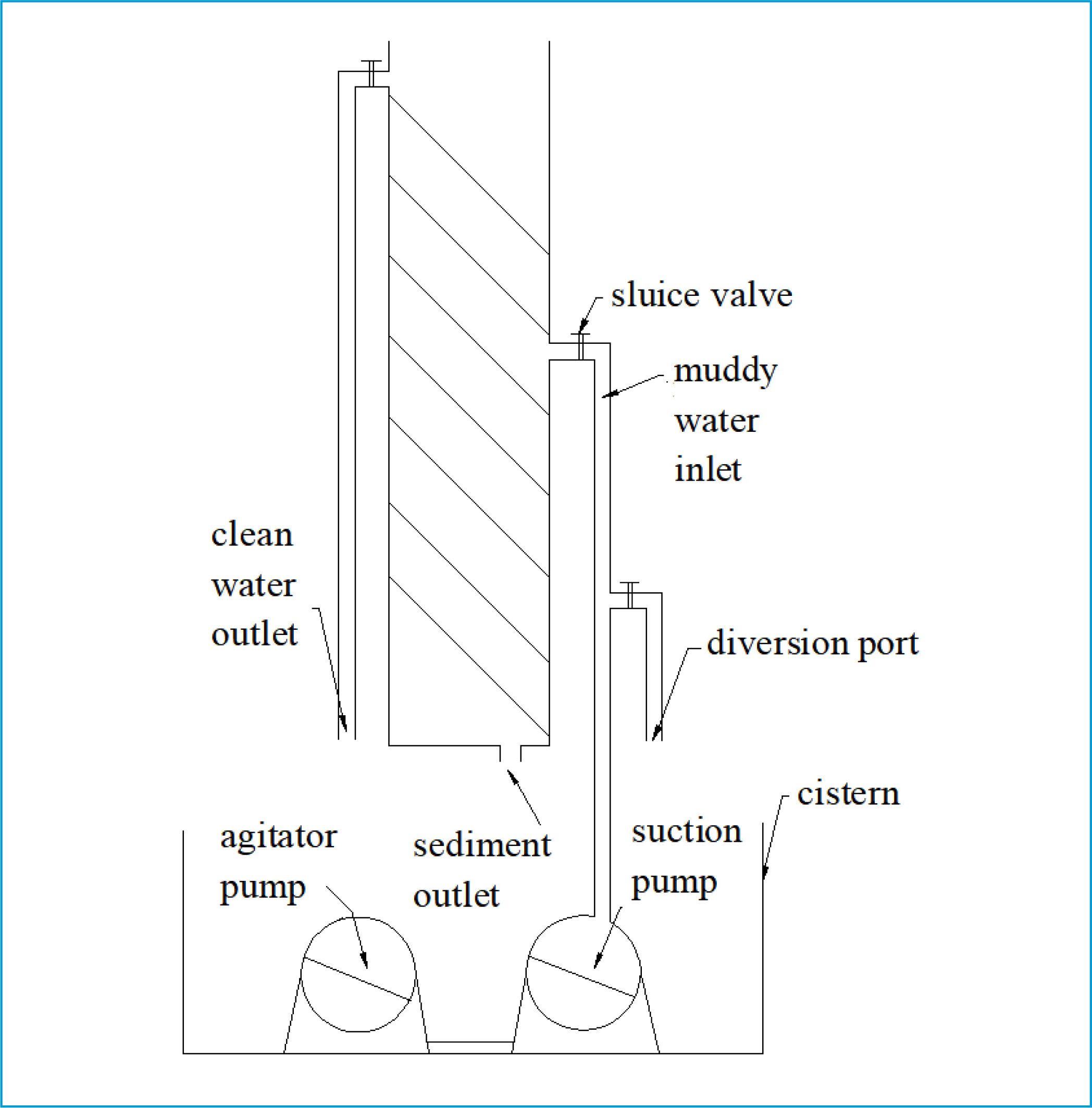
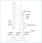
Figure 4 illustrates the water circulation system of the GPSD. The sticky sediment prepared for the test and distilled water were put into a water tank and mixed evenly with a mixing pump at first. Then, the resulting muddy water was delivered to the GPSD (or the ordinary tube) by a water pump for water–sediment separation. The sticky sediment separated was discharged to the water tank from the sediment outlet, and the clear water flew from the clear water outlet to the water tank. The sediment and clear water were mixed evenly again with the mixing pump, constituting a water circulation system.
Materials and instruments
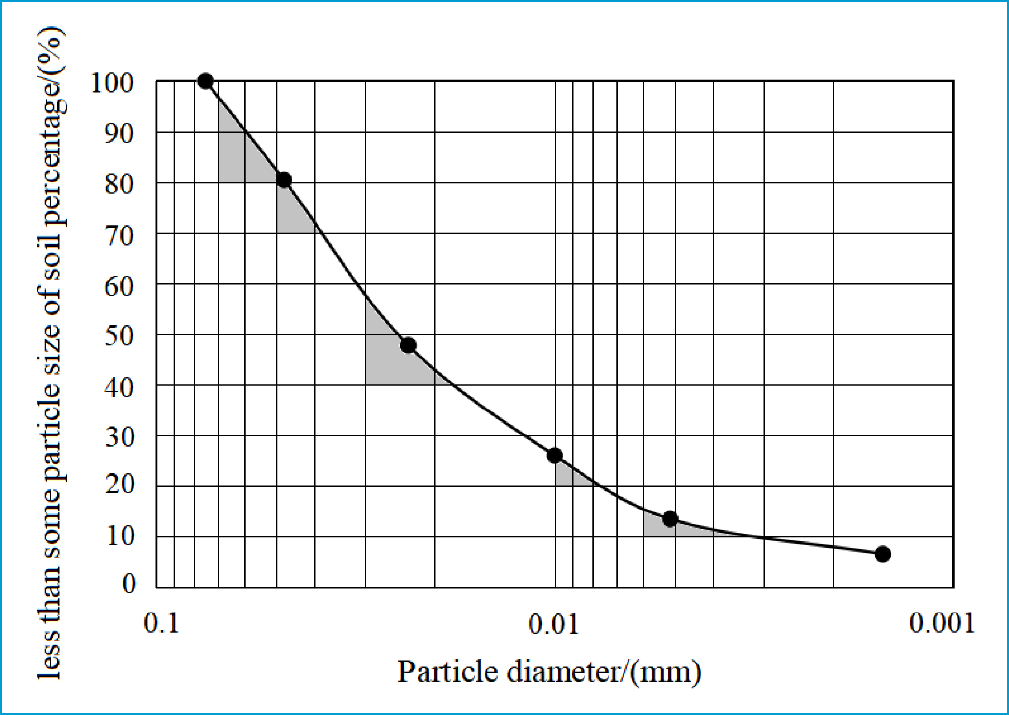
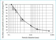
The GPSD applies to the treatment of sticky fine sediment (Tao; Qiu; Yang, 2015). Thus, natural loess from Xishan Mountain of Urumqi was taken as the experimental sediment. The particle size of the sediment was smaller than 0.076mm, and the median particle size D50 was 0.026mm. Figure 5 presents the size distribution graph of the sediment particles used in the experiment.
The main instruments used in the experiment included an electronic balance with a precision of 0.01g, a stopwatch, a 500ml beaker, a horizontal glass cover, a 250ml graduated cylinder, a 500ml conical flask, a pycnometer, a density meter, a flow velocimeter, a water pump, a mixing pump, an infrared thermometer, a digital camera, a tape measure, and a plastic bucket.
Conditions and methods
In the physical model experiments, the SC was 10 kg/m3 and the muddy water inlet flow (q) was 0.90m3/h (Tao et al., 2013b).
The principle of the pycnometer method was used in order to quickly and accurately measure the density of sediment. Each sample was weighed three times using the electronic balance with a precision of 0.01g, and the average of the three measurements was taken for the subsequent calculation. The density of sticky sediment was calculated by formula (1),
where pns (in kg/m3) is the density of sticky sediment, ms (in kg) is the mass of sticky sediment, mh (in kg) is the mass of the pycnometer and muddy water, mw (in kg) is the mass of the pycnometer and distilled water, and pw (in kg/m3) is the density of distilled water.
The displacement method was used to facilitate and improve the accuracy of the calculation of SC in muddy water tested. The volume of the conical flask was calculated by formula (2) first, and then the SC in muddy water was derived from formula (3),
In the above formulas, SC (in kg/m3) is the SC in muddy water, MZ+W (in kg) is the mass of the conical flask and muddy water, MZ+W (in kg) is the mass of the conical flask and distilled water, MZ (in kg) is the mass of the conical flask, VZ (in m3) is the volume of the conical flask, and pns and pw are the same with those in formula (1).
The Fr value is the ratio of the inertial force of water to gravity, and it is used to determine the dynamic feature of the water flow, such as whether it is rapid or slow. Its calculation formula is as follows:
where Fr is the Fr value, v (in cm/s) is the average flow velocity of the water flow, g is gravitational acceleration, which takes 981cm/s2, and h (in cm) is the average water depth.
Evaluation indicator
The water–sediment separation efficiency is currently an important indicator of the water–sediment separation performance of the gill-piece separating device. Its expression is as follows:
where n (in %) is water–sediment separation efficiency, SCin (in kg/m3) is the SC in the inflowing muddy water, and SCout (in kg/m3) is the SC in the outflowing clear water.
Numerical simulation
Mathematical models
The Gambit software was used to establish the three-dimensional models of GPSDs with gill-piece spacings of 30mm, 40mm, 50mm, 80mm, and 110mm. The length a, width b, height h, clear water channel e, sediment channel f, gill-piece spacing d, inclination in the length direction α, inclination in the width direction ß, muddy water inlet diameter, clear water outlet diameter, and sediment outlet diameter were modeled according to the dimensions of GPSDs used in the physical model experiments.
Based on the previous research on the GPSD (Luo et al., 2012), two mathematical models, namely, multiphase mixture model and turbulence model RNG k – ɛ, were used for calculation, analysis, and further verification in the CFX software.
The equations of continuity of the mixture model are
where pk is the density of the phase k, pm is the density of the mixed phase, Uk is the average velocity of the phase k, Um is the average velocity of the mixed phase, αk is the volume fraction of the phase k, and m is the quality transferred from the quality source.
The k and ɛ equations of the RNG k – ɛ model are
where Gk is the kinetic turbulent energy generated by the average velocity gradient, Gb is the kinetic turbulent energy generated by the buoyancy, YM is the influence of compressed turbulent fluctuation expansion on the total dissipation rate, R is the renormalization group, μeff is the turbulent viscosity, and σk and σɛ are the reciprocals of the effective Prandtl numbers of kinetic turbulent energy K and the dissipation rate ɛ, respectively. Both constants C2ɛ = 1.42 and C3ɛ = 1.68 are the default values.
Boundary conditions
In the CFX processor, water was set as the main phase, and sediment as the second phase. Sediment particles were assumed to be spheres, with an average size of 0.026 mm and a density of 2650 kg/m3. The boundary conditions are introduced in Figure 6.

-
Muddy water inlet boundary: The inlet was set as a velocity inlet as the inflowing muddy water was incompressible. According to the rate of flow of the muddy water at the inlet, the inlet flow, velocity, turbulence, and total pressure were set as 0.25 L/S, 0.81 m/s, 2.34×10⁻³ J/kg, and 839.9 Pa, respectively.
-
Clear water outlet boundary: This outlet was set as an average static pressure outlet. Its velocity, turbulence, and total pressure were set as 0.78 m/s, 4.90×10⁻³ J/kg, and 330.7 Pa, respectively.
-
Solid wall: The boundary condition of the solid walls (including gill-pieces, muddy water inlet, clear water outlet, sediment discharge, and interior and exterior side walls) in the GPSD was set as a wall.
-
Free surface: The free surface at the top of the GPSD remained horizontal and unchanged, and the velocities of the flow in all directions were zero. Thus, the rigid-lid hypothesis was adopted.
Mesh
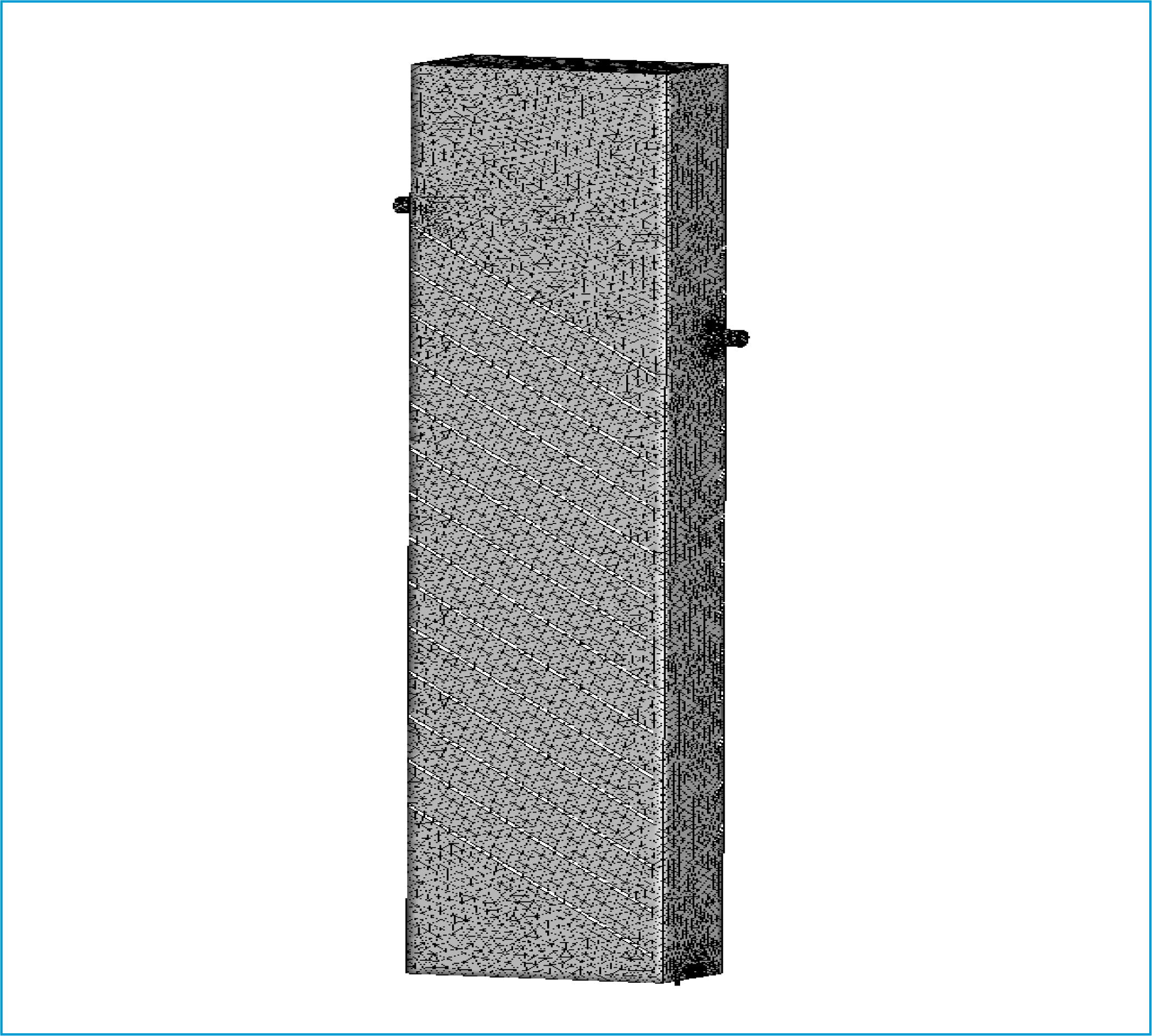
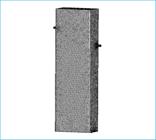
The GPSD has a complex interior structure, which was divided into unstructured meshes. The maximum face size (i.e., the maximum characteristic length of the divided units on the target surface) and the maximum body size (i.e., the maximum characteristic length of the divided units on the target body) were both set to be 0.0115. The total number of meshes was about 3 million. Figure 7 shows the meshes in the GPSD with a gill-piece spacing of 50 mm.
Calculation indicator
By numerical simulations, the average volume ratios of sediment at the inlet and outlet cross sections were obtained. Then, the average SC at the inlet and outlet cross sections was calculated from (11). Finally, the water–sediment separation efficiencies of GPSDs with different inlets were derived from (12):
In the above equations, ps is the sediment density (ps = 2650kg/m3), is the average volume ratio of sediment at the target cross section, (in kg/m3) is the average SC at the target cross section, η (in %) is the water–sediment separation efficiency, (in kg/m3) is the average SC at the muddy water inlet cross section, and (in kg/m3) is the average SC at the clear water outlet cross section.
RESULTS AND DISCUSSION
Experimental phenomenon and analysis
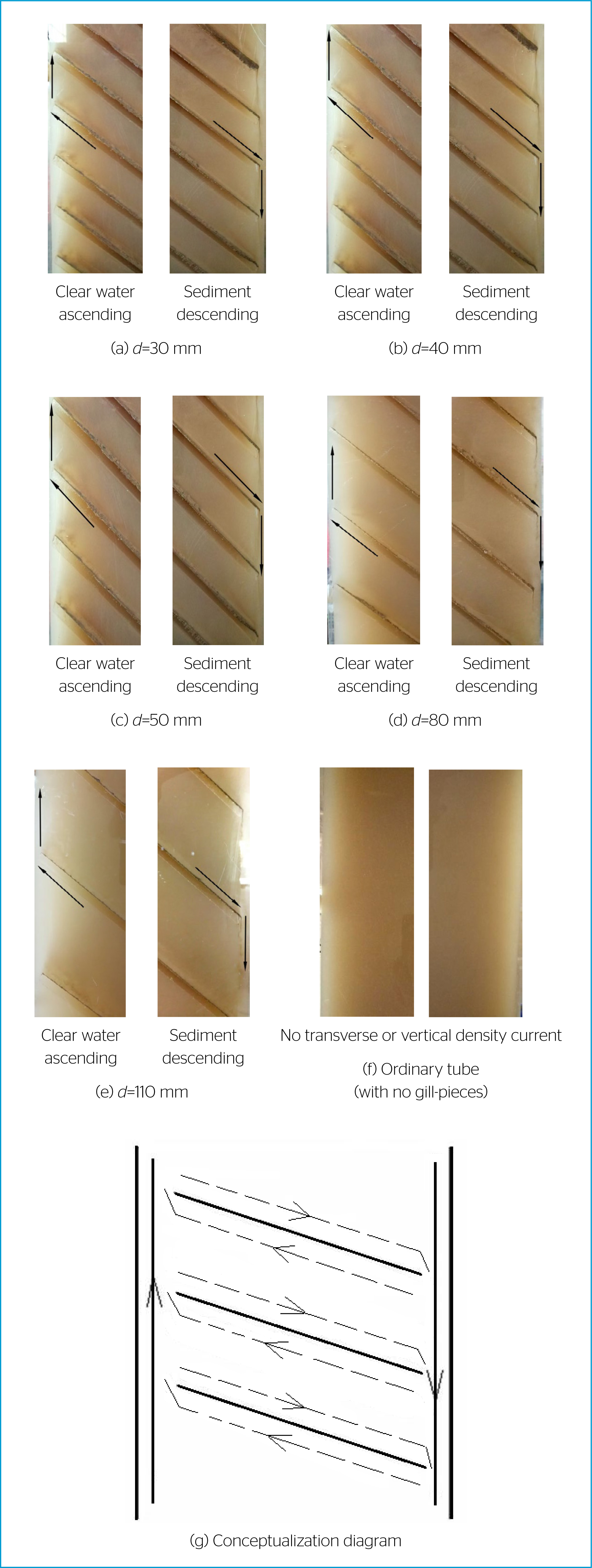
Figure 8 shows what happened in the middle positions of GPSDs with gill-piece spacings of 30, 40, 50, 80, and 110mm and the ordinary tube during the physical experiments.

Experimental phenomena in the middle positions of GPSDs with different gill-piece spacings and the ordinary tube at 126th min.
As shown in Figure 8(a) – (e), sticky fine sediment particles inside the GPSD were deposited on the upper surface of the gill-pieces, gathered to form a sediment flow, and settled to the sediment discharge through the triangular sediment descending channel. The clear water flow formed on the lower surface of the gill-pieces finally arrived at the clear water outlet through the triangular clear water ascending channel. There was a difference in density between the sediment flow (with a density of 2130.16kg/m³) and clear water flow (with a density of 997.05 kg/m³). Due to the downward movement of the flow with a larger density and the upward movement of the flow with a smaller density, an anisotropic flow phenomenon was observed. A counter-clockwise transversal density current (indicated by the dashed lines in Figure 8(g)) and a clockwise vertical density current (Zhang et al., 2019) (indicated by the solid lines in Figure 8(g)) were formed in the GPSD. However, there were no such phenomena in the ordinary tube without gill-pieces (Figure 8(f)).
Table 1 shows the average flow velocities and the Froude number (Fr) near middle positions (55cm depth) of GPSDs with different gill-piece spacings and the ordinary tube. It is obvious that the average flow velocities in the middle positions of all the GPSDs were smaller than 40cm/s. Especially, the average flow velocity of the GPSD with gill-piece spacings ranging between 30 and 50 mm was below 30 cm/s. A lower average flow velocity is conducive to water–sediment separation. However, the average flow velocity at the same position of the ordinary tube was significantly higher, 6.11–9.37 times that of GPSDs. The higher average flow velocity is unfavorable for sediment settling because sticky sediment does not flocculate at a flow velocity above 40cm/s. However, the sediment flocculates and settles well at a flow velocity below 30cm/s (Jiang; Yao; Tang, 2002). At the same position, the Fr values of GPSDs with different gill-piece spacings were all smaller than 1. The water flow was slow, and turbulence inside the device was small, which facilitated the formation of the density current. The Froude number (Fr) of the ordinary tube was greater than 1. The water flow was rapid, and the turbulence was large. The sticky sediment was evenly suspended in the ordinary tube, and no density current was generated.
Average flow velocities and Fr values at the middle part of GPSDs with different gill-piece spacings and the ordinary tube.
Experimental results and analysis
Table 2 compares the water–sediment separation efficiencies among GPSDs with different gill-piece spacings and the rectangular ordinary tube. The following conclusions were drawn from Table 2. (1) The water–sediment separation efficiencies of GPSDs with gill-piece spacings of 30, 40, 50, 80, and 110mm were 1.71–3.74, 1.70–3.74, 1.72–3.74, 1.41–2.61, and 1.27–2.09 times higher than that of the ordinary tube, respectively. (2) The GPSD with a gill-piece spacing of 30mm had the highest water–sediment separation efficiency (35.47 %), which was 1.22–1.43 and 1.36–1.78 times higher than that of the device with gill-piece spacings of 80 and 110mm, respectively. (3) The difference in water–sediment separation efficiency was small between GPSDs with gill-piece spacings of 30 and 40 mm. The water-sediment separation efficiencies of GPSDs with gill-piece spacings of 30, 40, and 50mm were 35.47%, 35.45%, and 35.41%, respectively
Comparison of water–sediment separation efficiencies among GPSDs with different gill-piece spacings and the ordinary tube.
There are several reasons for the abovementioned experimental results. (1) The gill-pieces broke up the strong network formed by settling sticky sediment, making the particles clump, which helped sediment settle faster. The gill-pieces also increased the wetted perimeter of the flow cross section inside the device and reduced both the hydraulic radius and the Reynolds number, thus improving the hydraulic conditions for the movement of sticky fine sediment particles, promoting the formation of the density current and enhancing the water–sediment separation efficiency. (2) The water–sediment separation efficiency was directly proportional to the horizontal area covered by sediment in the settler within a certain range (Xie et al., 2019). The projected horizontal areas covered by sediment were 380000, 304000, 266000, 171000, 133000, and 20000mm2 in GPSDs with gill-piece spacings of 30, 40, 50, 80, and 110mm and the ordinary tube, respectively. It thus can be derived that within a certain range, the gill-piece spacing is negatively correlated with the projected horizontal area in the GPSD and positively correlated with the water–sediment efficiency. (3) The mixed layer between two gill-pieces (the interlayer between the sediment and clear water flows shown in Figure 9) also affected the water–sediment separation process in the GPSD. The mixed layer became thinner with the decrease of the distance between gill-pieces, leading to the formation of a strong shear force between the descending sediment and the ascending clear water flow along the long side of the gill-pieces (Guo, 2018). As a result, the sediment and clear water flows that originally moved along their respective trajectories between gill-pieces showed the tendency to mix. It interfered with the settling process in flowing water conditions. Within the GPSD, the sediment's fast sinking and clear water's rising movements were blocked. Therefore, the water–sediment separation efficiencies of GPSDs changed slightly with the increase of the gill-piece spacing from 30 to 50mm.
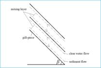
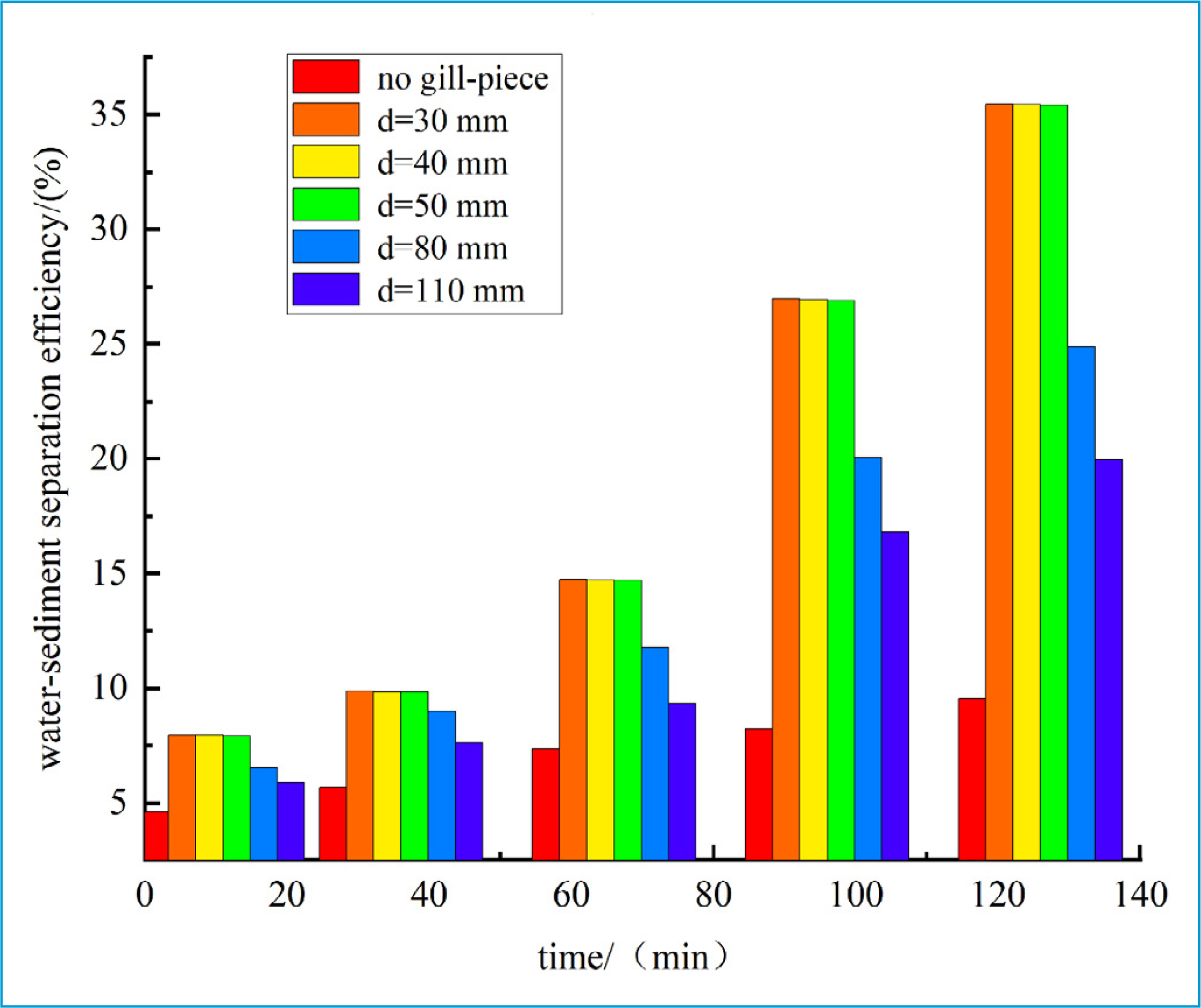
Figure 10 depicts the change pattern of water–sediment separation efficiency over time in GPSDs with gill-piece spacings of 30–110 mm and the ordinary tube. As shown in Figure 10, the change in water–sediment separation efficiency significantly decreased with the increase of the gill-piece spacing. The reason is that the vertical height of adjacent gill-pieces increased as the gill-piece spacing enlarged. Under the influence of water flow turbulence at the muddy water inlet, the equilibrium state was disrupted, and the flocs were destroyed (Wang et al., 2019). Meanwhile, it was more difficult for the flocs to fall, which prolonged the time for sediment to flocculate and settle and reduced the settling speed. Moreover, the increased gill-piece spacing made the water circulation environment where sediment settled down and clear water moved upward in the GPSD more unstable. Consequently, the change range of the water–sediment separation efficiency in GPSDs with gill-piece spacings of 80 and 110 mm was smaller than that in the GPSD with gill-piece spacings of 30–50.
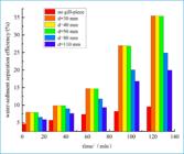
Comparison of water–sediment separation efficiencies of different gill-piece spacings and at different times.
Calculation results and analysis
Velocity field and analysis
(1) The distribution of velocity vectors in the middle position of GPSDs with different gill-piece spacings
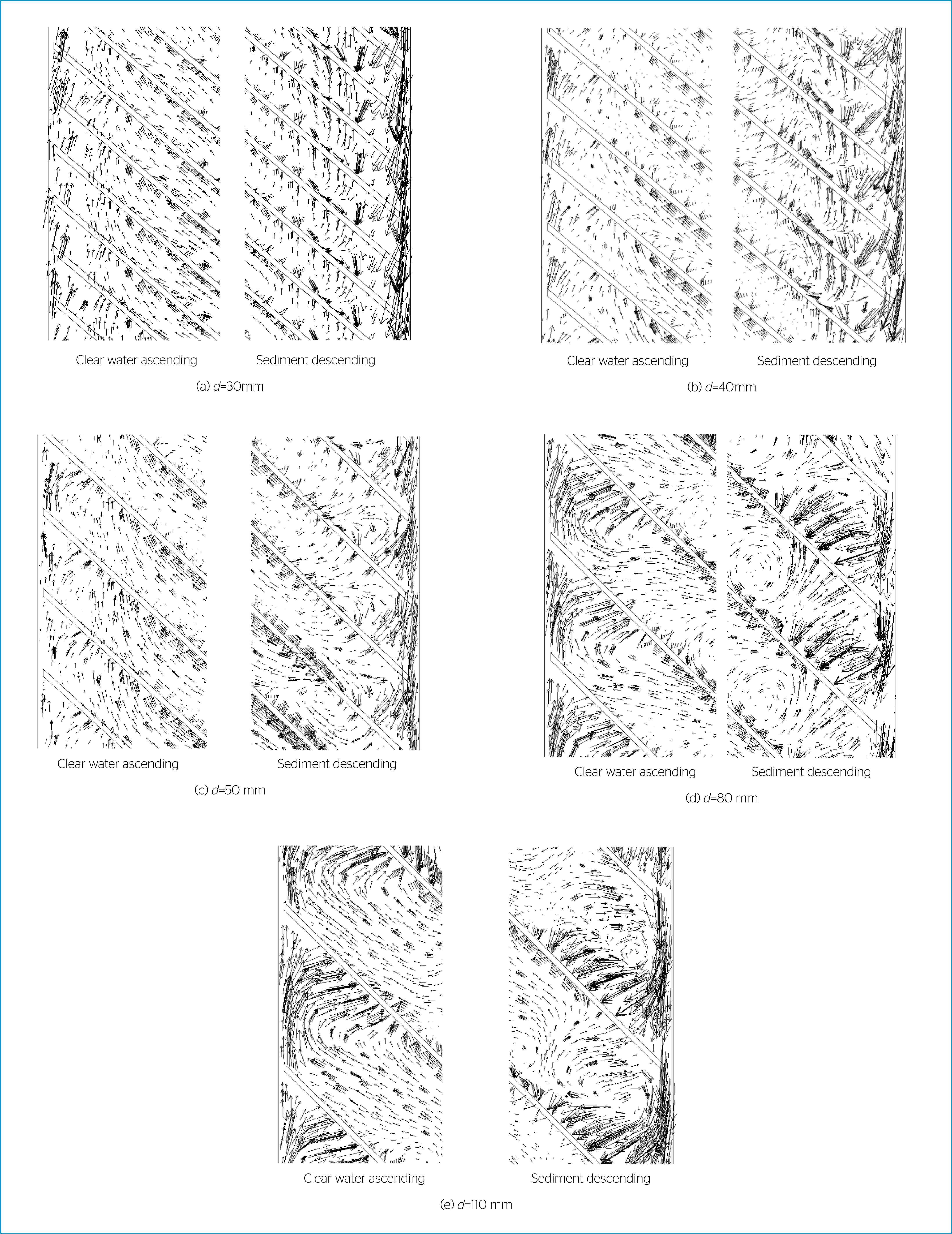
Figure 11 shows the distribution of velocity vectors on the cross section of Y=0.41dm in the middle position of GPSDs with different gill-piece spacings at the end of the iteration. It is evident that velocity vectors were distributed differently along the width direction in GPSDs with different gill-piece spacings.
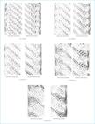
Velocity vector distribution on the cross section of Y=0.41 dm at different gill-piece spacings.
In Figure 11(a–c), the clear water flow is mostly visible on the left, while the sediment flow dominates the right side. The clear water flowed from the lower surface to the highest end of each gill piece, converged to the clear water channel, and then did upward movement. The sediment flowed downward along the top of each gill-piece, collecting at the lower end before sinking further. Therefore, less-disturbed transverse and vertical density currents were generated due to the descending sediment flow and ascending clear water flow. This finding matches what was seen in the indoor model experiment. In Figure 11(d) and (e), a large semi-vortex (inward reflux) was formed between two gill-pieces on both the left and right pictures. The semi-vortex made the rising clear water flow in the clear water channel and the descending sediment flow in the sediment channel return to the upper and lower surfaces of the gill-pieces, respectively. It greatly hindered the separation of clear water and sediment.
It was found that the gill-piece spacing was positively correlated with the reflux angle between two gill-pieces and the size of the semi-vortex. This finding proves once again that when the volumes of two GPSDs are the same, the one whose flow cross section has a smaller wetted perimeter has a larger hydraulic radius. Therefore, at the same flow velocity v, increasing greatly the Reynolds number (re) will make the water flow more turbulent and destroy the density current in the GPSD, thereby impeding sediment settling and clear water ascending. To achieve rapid and effective separation of water and sediment, the sediment and clear water flows should follow their respective trajectories and not interfere with each other. Taken above, the gill-piece spacing was determined to be 30–50mm so that the interior velocity flow field satisfied the above conditions.
(2) The distribution map of velocities on the Y cross section (length direction)
Figure 12 illustrates the distribution of velocities on the cross section of Y=0.61 dm in GPSDs with different gill-piece spacings under flowing water conditions. In the figure, the velocity v is the resultant velocity of velocities in the X, Y, and Z directions. The figure shows the distribution of different velocities in the GPSD. It was found that as the gill-piece spacing increased, the distribution of velocities near the top of the GPSD became increasingly complex. As a result, the stability of the water flows near the inlet and outlet was reduced.

The distribution map of velocities on the Y cross section at different gill-piece spacings.
Meanwhile, with the increase of the gill-piece spacing, the velocity distribution at the left side of the space between gill-pieces gradually formed a sickle-like shape, while that at the right side showed an inverted hook shape diagonally opposite to the left side. Turbulence was generated by sediment moving near the bottom of gill-pieces and in the sediment channel, as well as clear water flowing above the gill-pieces and in the clear water channel.
In GPSDs with gill-piece spacings of 80 and 110 mm, the velocity flow fields interfered with each other to varying degrees, making it difficult to separate water and sediment rapidly and effectively. Moreover, on the cross section of Y=0.61 dm, the turbulence range of the velocity flow field at the bottom of each gill piece also expanded with the increase of the gill-piece spacing. The maximum settling speed of sediment at the bottom of the GPSD with gill-piece spacings of 30–50 mm was about 0.084–0.085 m/s. The maximum settling speeds of sediment at the bottom of GPSDs with gill-piece spacings of 80 and 110 mm were both about 0.075 m/s. However, due to the small size of the sediment discharges tested in the experiment, the settling speeds at the right sediment discharges at the bottom were similar (about 0.092 m/s). Generally, the GPSD with a gill-piece spacing of 50 mm had a faster sediment settling speed than GPSDs with gill-piece spacings of 80 and 110 mm.
Concentration distribution and analysis
(1) Concentration distribution on the Y cross section (length direction)
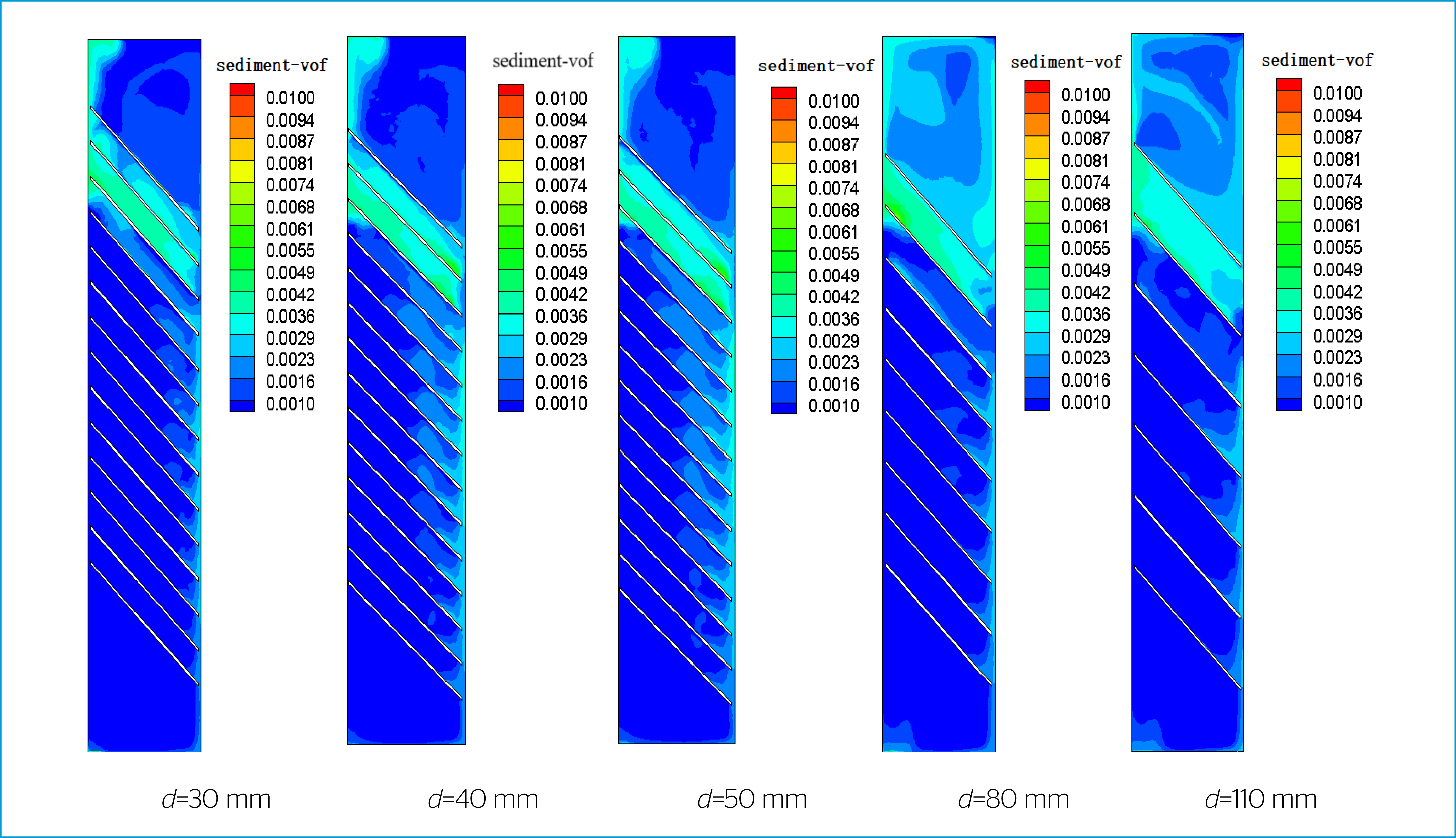
Figure 13 shows the volume concentration distribution of sediment on the cross section of Y=0.61 (width direction) at the end of the iteration. In the figure, the vertical column on the right indicates the volume fraction of sediment (sediment-vof).
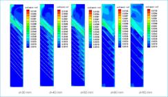
Volume concentration distribution of sediment on the Y cross section at different gill-piece spacings.
As shown in Figure 13, the volume concentrations of sediment were low near the top and outlet on the cross section of the GPSD with gill-piece spacings of 30–50 mm, and the volume fraction was mainly 0.0016. However, the distribution of volume concentrations was complex in the same areas of GPSDs with gill-piece spacings of 80 and 110 mm, and the volume fraction was mainly 0.0023. It is evident that the SC on the lower and upper surfaces of gill-pieces gradually decreased and increased with the increase of the gill-piece spacing, respectively. The SC at all sediment discharges at the bottom of GPSDs and the concentration distributions in all concentration fields nearby were basically the same. However, the concentration was high in the same areas at the left end of the bottom far away from the sediment discharge in the GPSDs with gill-piece spacings of 80 and 110 mm.
Based on the above analyses, enlarging the gill-piece spacing increased the vertical distance of channels in the gill-pieces, accelerated the settling of the sediment flow on the upper surface of gill-pieces under the action of gravity, and thus improved the falling speed of the mixed sediment flow in the sediment channel. The mixed sediment flow did accelerate the downward movement and flushed the bottom. As a result, the sediment shifted to the left under the action of the right-angled sidewalls at the bottom. The accumulation of sediment in a small area on the left side hindered its timely and effective discharge at the bottom. Meanwhile, the increasing speed of sediment falling and gathering between two gill-pieces further enhanced the disturbance to the water body, resulting in a reduction of the effective sedimentation area in the GPSD and the intensity of water–sediment separation activities. The concentration near the clear water outlet at the top of the GPSD gradually increased, which worsened the water–sediment separation effect.
(2) Concentration distribution on inlet and outlet cross sections at different gill-piece spacings
Figure 14 illustrates the concentration distribution at the ends of iterations on the cylindrical inlet and outlet cross sections of GPSDs with varying gill-piece spacings. It is evident that the concentration distributions on the inlet cross sections of GPSDs with different gill-piece spacings were basically the same. To be specific, the same volume of sediment uniformly spread throughout the entire circular surface, and the average volume ratio was all 0.004. The reason is that the original sediment concentrations in muddy water flowing into the system through the five inlets were the same and the sticky sediment was suspended evenly in muddy water.
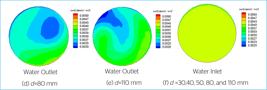
Volume concentration distribution of sediment on inlet and outlet cross sections at different gill-piece spacings.
In Figure 14(a–c), the concentration of sediment was higher and showed a crescent-shaped distribution at the edge of the circular area, but the concentration was lower in the middle round-like area of the outlet cross section. Generally, the concentration gradually decreased from the edge to the center, and the average volume ratio of sediment on this cross section was 0.0026. In particular, Figure 14(b) displays a somewhat larger extent of low-concentration regions. The concentration distribution of sediment on the outlet cross section shown in Figure 14(d) was similar to that in Figure 14(a–c). However, the GPSD with a gill-piece spacing of 80 mm had a larger high-concentration area and a smaller low-concentration area than the GPSD with gill-piece spacings of 30–50 mm. The average volume ratio for the GPSD with 80mm gill-piece spacing was 0.003 across its cross section.
The concentration distribution in Figure 14(e) was greatly different from that in Figure 14(a–d); the high concentration area almost encircled the edge of the circular cross section and extended to the upper left corner. The low concentration area gathered in the upper left corner, forming a hole shape. By the comparison of the abovementioned outlet cross sections, it was found that among the GPSDs with different gill-piece spacings, the one with gill-piece spacings of 30–50 mm had a larger medium- to low-concentration area and a smaller high-concentration area on the cross section, the lowest average volume fraction of sediment, and the best water–sediment separation effect.
(3) The average SC on inlet and outlet cross sections and water–sediment separation efficiencies at different gill-piece spacings.
Table 3 compares the average SC on inlet and outlet cross sections and water–sediment separation efficiencies (simulated) of GPSDs with different gill-piece spacings at the end of the iteration. As an important indicator of the performance of GPSDs, the value of the water–sediment separation efficiency indicated the water–sediment separation effect of the device.
Comparison of average SC on the inlet and outlet cross sections and water–sediment separation efficiencies among GPSDs with different gill-piece spacings.
Relative error
(1) Comparison of physical experimental data with numerical simulations
To further verify the calculation accuracy, the calculation results of the five GPSDs with different gill-piece spacings were compared with the physical experimental results. The reliability was indicated by the relative error, which is expressed as (13):
where H is the relative error, η is the simulated water–sediment separation efficiency, and n is the water–sediment separation efficiency obtained by physical experiments.
Table 4 shows the relative error between simulated and experimental results. It was found that the relative errors of the three GPSDs with different gill-piece spacings were relatively small, ranging from 0.34% to 1.61% (below 2%).
Relative errors between results obtained by different mathematical models and physical experiments.
(2) PPR comparative analysis
Projection Pursuit Regression (PPR) represents a nonlinear regression technique that uncovers the underlying structure within data by identifying low-dimensional projections of the data. The fundamental formulation is as follows:
Let y denote the dependent variable and x represent the independent variable in a p-dimensional space. The PPR model is formulated as shown in Equation (14):
Within this equation, ; M signifies the optimal number of ridge functions; γi represents the contribution weight coefficient for the numerical function; fi denotes the ridge function; and has a mean of 0, and it possesses a variance of 1.
PPR modeling evaluated the efficiency of water–sand separation in five different gill-piece spacing configurations. To achieve greater prediction accuracy, the smoothing coefficient, indicative of projection sensitivity, was set to Span = 0.6, with the initial projection direction initialized at M=3, converging to a final projection direction of MU=3. The PPR model parameters utilized for the computations were Nm=5, P=3, Q=1, M=5, and MU=3.
Table 5 presents the outcomes of the PPR model calculations. As evident from Tables 4 and 5, the measured and predicted values of water–sand separation efficiency demonstrate a satisfactory fit, with absolute errors ≤ ±0.81% and relative errors ≤ ±2.85%. All nine experimental data points achieved acceptable prediction accuracies. Consequently, the PPR model effectively mirrors the measured values, affirming its reliability for this particular experimental context.
To sum up, the experimental process in this study is relatively precise and reasonable, the experimental results are accurate and valid, and the theories are reliable. The results prove that the mixture and RNG k – ɛ coupled model is the best mathematical model for simulating the two-phase (water and sediment) flow field in GPSDs under flowing water conditions.
CONCLUSIONS
In this paper, physical experiments and numerical simulations were made to explore the water–sediment separation efficiencies of GPSDs with different gill-piece spacings and the rectangular ordinary tube. The following conclusions are drawn.
-
The water–sediment separation efficiencies of GPSDs with gill-piece spacings of 30, 40, 50, 80, and 110 mm are 1.71–3.74, 1.70–3.74, 1.72–3.74, 1.41–2.61, and 1.27–2.09 times higher than that of the ordinary tube. The water–sediment separation efficiency of the GPSD with a gill-piece spacing of 50 mm is 1.21–1.42 and 1.35–1.77 times higher than that of GPSDs with gill-piece spacings of 80 and 110 mm in the time range of 10–126 min, respectively.
-
The simulated flow field pattern is similar to the density current observed during the experiment. There is a small error between the simulated and experimental water–sediment separation efficiency. It demonstrates that the results of this study are accurate and valid, theories are reliable, and the mixture and RNG k – ɛ coupled model is the best mathematical model for simulating the two-phase (water and sediment) flow field in GPSDs under flowing water conditions.
-
With the increase of the gill-piece spacing from 30mm to 50mm, the water–sediment separation efficiency changes slightly. The number of gill-pieces increases with the decrease of the gill-piece spacing when the GPSD volume is fixed. In practical engineering, the GPSD with a gill-piece spacing of 50mm is recommended considering both the settling effect and economic benefits.
ACKNOWLEDGMENTS
Project approval number: 2023AH053043 (Department of Education of Anhui Province).
REFERENCES
-
AN, Lin, YAO, Zhanyu, ZHANG, Pei; JIA, Shuo; ZHAO, Jieyun, LIU, Zhen; ZHANG, Zequn. Study on Atmospheric Water Resource Variation Characteristics in China and Influencing Factors of Precipitation Efficiency of Hydrometeors. Water, v. 15, n. 6, 1020, 2023. https://doi.org/10.3390/W15061020
» https://doi.org/10.3390/W15061020 -
BOVÉ, Josep; ARBAT, Gerard; PUJOL, Toni; DURAN-ROS, Miquel; DE CARTAGENA, Francisco Ramírez; VELAYOS, Joaquim; PUIG-BARGUÉS, Jaume. Reducing energy requirements for sand filtration in microirrigation: Improving the underdrain and packing. Biosystems Engineering, v. 140, p. 67-78, 2015. https://doi.org/10.1016/j.biosystemseng.2015.09.008
» https://doi.org/10.1016/j.biosystemseng.2015.09.008 -
DURAN-ROS, Miquel; ARBAT, Gerard; BARRAGÁN, Javier D.; RAMÍREZ DE CARTAGENA, Francisco; PUIG-BARGUÉS, Jaume. Assessment of head loss equations developed with dimensional analysis for micro irrigation filters using effluents. Biosystems Engineering, v. 106, n. 4, p. 521-526, 2010. https://doi.org/10.1016/j.biosystemseng.2010.06.001
» https://doi.org/10.1016/j.biosystemseng.2010.06.001 -
DURAN-ROS, Miquel; PUIG-BARGUÉS, Jaume; ARBAT, Gerard; BARRAGÁN, Javier D.; RAMÍREZ DE CARTAGENA, Francisco. Effect of filter, emitter and location on clogging when using effluents. Agricultural Water Management, v. 96, n. 1, p. 67-79, 2009. https://doi.org/10.1016/j.agwat.2008.06.005
» https://doi.org/10.1016/j.agwat.2008.06.005 - GUO, Chao. Pesquisa sobre o processo de floculação e sedimentação e mecanismo de controle de sedimentos viscosos Shanghai: East China Normal University, 2018.
-
HOU, Peng; PUIG-BARGUÉS, Jaume; XIAO, Yang; XUE, Tao; WANG, Jinyan; SONG, Peng; LI, Yunkai. An improved design of irrigation centrifugal filter for separating water and fine sediment: appropriately increase head loss for high efficiency. Irrigation Science, v. 40, n. 2, p. 151-161, 2022. https://doi.org/10.1007/S00271-021-00765-9
» https://doi.org/10.1007/S00271-021-00765-9 -
HUI, Xin.; ZHENG, Yudong.; YAN, Haijun. Water distributions of low-pressure sprinklers as affected by the maize canopy under a centre pivot irrigation system. Agricultural Water Management, v. 245, 2021. https://doi.org/10.1016/J.AGWAT.2020.106646
» https://doi.org/10.1016/J.AGWAT.2020.106646 -
INDAH, Nindia Noor; JUNIAWAN, Asyhar Sururi; SUSILANINGTYAS, Hanifah; BUDHIJANTO, Wiratni; MARBELIA, Lisendra. Performance of Hybrid Mesh Filter Bioreactor For Textile Wastewater Treatment. IOP Conference Series: Earth and Environmental Science, v. 1275, n. 1, 2023. https://doi.org/10.1088/1755-1315/1275/1/012033
» https://doi.org/10.1088/1755-1315/1275/1/012033 -
IYER, J. Chandrashekhar; JAMES, E. J. Model studies for the design of inlet transition of settling basins of hydropower projects in high sediment yield areas: a review. ISH Journal of Hydraulic Engineering, v. 29, n. 3, p. 351-359, 2023. https://doi.org/10.1080/09715010.2022.2084350
» https://doi.org/10.1080/09715010.2022.2084350 -
JIANG, Guojun; YAO, Yanming; TANG, Ziwen. Análise de fatores que afetam a floculação e sedimentação de sedimentos finos no estuário do Rio Yangtze. Journal of Oceanography, v. 24, n. 4, p. 51-57, 2002. https://doi.org/10.3321/j.issn:0253-4193.2002.04.006
» https://doi.org/10.3321/j.issn:0253-4193.2002.04.006 -
KASARANENI, Varun K.; ANAYA, Nelson M.; TALIANI, Maria. Enhancing Point-of-Use Sand Filters through Integration of Copper Mesh. Water, v. 16, n. 15, 2188, 2024. https://doi.org/10.3390/W16152188
» https://doi.org/10.3390/W16152188 -
KUMAR, Sanjeev; OJHA, Chandra Shekhar Prasad; TIWARI, Nand Kumar; RANJAN, Subodh. Exploring the potential of artificial intelligence techniques in prediction of the removal efficiency of vortex tube silt ejector. International Journal of Sediment Research, v. 38, n. 4, p. 615-627, 2023. https://doi.org/10.1016/j.ijsrc.2023.03.001
» https://doi.org/10.1016/j.ijsrc.2023.03.001 -
LI, Hao; MA, Zhengjun; ZHANG, Guangsong; CHEN, Jiayao; LU, Yunchao; LI, Peng. Performance of a Drip Irrigation System under the Co-Application of Water, Fertilizer, and Air. Horticulturae, v. 10, n. 1, 6, 2024. https://doi.org/10.3390/horticulturae10010006
» https://doi.org/10.3390/horticulturae10010006 - LUO, Fei; JIANG, Quanquan; GUO, Hua; QIU, Xiuyun; LI, Lin. Simulação numérica tridimensional do campo de fluxo água-areia com única lâmina de lamela separadora quando há fluxo de entrada e saída. Journal of Water Resources and Water Engineering, v. 23, n. 3, p. 77-80, 2012.
-
PUIG-BARGUÉS, Jaume; BARRAGÁN, Javier D.; RAMÍREZ DE CARTAGENA, Francisco. Development of Equations for calculating the Head Loss in Effluent Filtration in Microirrigation Systems using Dimensional Analysis. Biosystems Engineering, v. 92, n. 3, p. 383-390, 2005. https://doi.org/10.1016/j.biosystemseng.2005.07.009
» https://doi.org/10.1016/j.biosystemseng.2005.07.009 -
QIU, Xiuyun; GONG, Shouyuan; YAN, Yecheng; YANG, Lixing. Pesquisa sobre um novo dispositivo de separação água-areia. Journal of Xinjiang Agricultural University, v. 30, n. 1, p. 68-70, 2007. https://doi.org/10.3969/j.issn.1007-8614.2007.01.017
» https://doi.org/10.3969/j.issn.1007-8614.2007.01.017 -
SHARAFATI, Ahmad; TAFAROJNORUZ, Ali; SHOURIAN, Mojtaba; YASEEN, Zaher Mundher. Simulation of the depth scouring downstream sluice gate: The validation of newly developed data-intelligent models. Journal of Hydro-environment Research, v. 29, p. 20-30, 2020. https://doi.org/10.1016/j.jher.2019.11.002
» https://doi.org/10.1016/j.jher.2019.11.002 -
SHI, Kaili; LU, Tiangang; ZHENG, Wengang; ZHANG, Xin; ZHANGZHONG, Lili. A Review of the Category, Mechanism, and Controlling Methods of Chemical Clogging in Drip Irrigation System. Agriculture, v. 12, n. 2, 202, 2022. https://doi.org/10.3390/agriculture12020202
» https://doi.org/10.3390/agriculture12020202 - TAO, Hongfei. Análise numérica e pesquisa experimental sobre o campo de fluxo água-areia de lamelas separadoras Xinjiang: Xinjiang Agricultural University, 2014.
- TAO, Hongfei; QIU, Xiuyun; HE, Zhaoqing; LI, Weipeng; XU, Linlin. Experimento sobre o efeito da concentração de areia na separação água-areia de lamelas separadoras. Hydropower Energy Science, v. 31, n. 7, p. 93-95, 2013a.
-
TAO, Hongfei; QIU, Xiuyun; LI, Qiao; TAN, Yihai; WANG, Miao. Simulação numérica tridimensional do campo de fluxo dentro de lamelas separadoras com diferentes espaçamentos entre lâminas. Journal of Agricultural Machinery, v. 45, n. 6, p. 183-189, 2014. https://doi.org/10.6041/j.issn.1000-1298.2014.06.028
» https://doi.org/10.6041/j.issn.1000-1298.2014.06.028 - TAO, Hongfei; QIU, Xiuyun; LI, Qiao; SU, Jianjiang. Simulação numérica tridimensional do campo de fluxo dentro de lamelas separadoras sob diferentes ângulos de inclinação das lâminas. Hydropower Energy Science, v. 33, n. 1, p. 157-161, 2015.
- TAO, Hongfei; QIU, Xiuyun; YANG, Haihua. Simulação numérica tridimensional do campo de fluxo dentro de uma lamela separadora com diferentes concentrações de areia em água turbida. Journal of Hydropower Generation, v. 34, n. 2, p. 64-71, 2015.
- TAO, Hongfei; QIU, Xiuyun; LI, Weipeng; HE, Zhaoqing; XU, Linlin. Ensaio de sedimentação hidrostática do espaçamento ótimo entre lâminas de lamelas separadoras. Progress of water conservancy and hydropower science and technology, v. 33, n. 4, p. 49-53, 2013b.
-
TAO, Hongfei; QIU, Xiuyun; ZHAO, Lina; LI, Lin. Simulação numérica do campo de fluxo dentro de uma lamela separadora água-areia. Journal of Agricultural Engineering, v. 29, n. 17, p. 38-46, 2013c. https://doi.org/10.3969/j.issn.1002-6819.2013.17.006
» https://doi.org/10.3969/j.issn.1002-6819.2013.17.006 -
WANG, Yafei; ZHANG, Yangkai; WANG, Wenjuan; LIU, Zhengguang; YU, Xingjiao; LI, Henan; WANG, Wene; HU, Xiaotao. A Review of Optimal Design for Large-Scale Micro-Irrigation Pipe Network Systems. Agronomy, v. 13, n. 12, 2966, 2023. https://doi.org/10.3390/agronomy13122966
» https://doi.org/10.3390/agronomy13122966 -
WANG, Yayue; LI, Wenhao; TAN, Ming; SONG, Dahai. Research on the Application of Centrifugal Filters in Drip Irrigation Systems. Journal of Irrigation and Drainage, v. 38, n. S2, p. 73-77, 2019. https://doi.org/10.13522/j.cnki.ggps.20190228
» https://doi.org/10.13522/j.cnki.ggps.20190228 - WANG, Yilin. Simulação numérica de tanque de sedimentação de placas inclinadas baseada em CFD Dissertação (Mestrado em Engenharia Civil) – Hebei Construction Engineering Institute, 2022.
-
WEN-YONG, Wu; YAN, Huang; HONG-LU, Liu; SHI-YANG, Yin; YONG, Niu. Reclaimed Water Filtration Efficiency and Drip Irrigation Emitter Performance with Different Combinations of Sand and Disc Filters. Irrigation and Drainage, v. 64, n. 3, p. 362-369, 2015. https://doi.org/10.1002/ird.1909
» https://doi.org/10.1002/ird.1909 -
XIE, Xiang-ping; WEI, Fang-qiang; WANG, Xiao-jun; YANG, Hong-juan. Determination of optimal grid opening width for herringbone water-sediment separation structures based on sediment separation efficiency. Journal of Mountain Science, v. 16, n. 3, p. 619-629, 2019. https://doi.org/10.1007/s11629-018-5038-7
» https://doi.org/10.1007/s11629-018-5038-7 -
XU, Xin; WANG, Qin; ZHANG, Jinzhu; ZONG, Rui; LIU, Ningning; WANG, Zhenhua. Experimental Study of Filtration Performance of Disc Filter with Discrete Channel Structure. Journal of Irrigation and Drainage Engineering, v. 149, n. 7, 2023. https://doi.org/10.1061/JIDEDH.IRENG-10064
» https://doi.org/10.1061/JIDEDH.IRENG-10064 -
YAN, Yuecheng; QIU, Xiuyun; ZHANG, Xiang; GONG, Shouyuan. An experimental study on the influence of the width of the GPSD sediment and sand settling channel in two-phase flow separation on mud and sand separation. Journal of Xinjiang Agricultural University, v. 34, n. 6, p. 526-528, 2011. https://doi.org/10.3969/j.issn.1007-8614.2011.06.015
» https://doi.org/10.3969/j.issn.1007-8614.2011.06.015 -
YOUNES, Aminpour; DARYA, Dehghan; ENRIQUE, Playán; MAROUFPOOR, Eisa. Estimation of wind drift and evaporation losses of sprinkler irrigation systems using dimensional analysis. Agricultural Water Management, v. 289, 108518, 2023. https://doi.org/10.1016/j.agwat.2023.108518
» https://doi.org/10.1016/j.agwat.2023.108518 -
YURDEM, Huseyin; DEMIR, Vedat; DEGIRMENCIOGLU, Adnan Degirmencioglu. Development of a mathematical model to predict head losses from disc filters in drip irrigation systems using dimensional analysis. Biosystems Engineering, v. 100, n. 1, p. 14-23, 2008. https://doi.org/10.1016/j.biosystemseng.2008.01.003
» https://doi.org/10.1016/j.biosystemseng.2008.01.003 -
ZAHRIM, A. Y.; TIZAOUI, C.; HILAL, N. Removal of Highly Concentrated Industrial Grade Leather Dye: Study on Several Flocculation and Sand Filtration Parameters. Separation Science and Technology, v. 46, n. 6, p. 883-892, 2011. https://doi.org/10.1080/01496395.2010.550596
» https://doi.org/10.1080/01496395.2010.550596 -
ZHAI, Li-chao; LÜ, Li-hua; DONG, Zhi-qiang; ZHANG, Li-hua; ZHANG, Jing-ting; JIA, Xiu-ling; ZHANG, Zheng-bin. The water-saving potential of using micro-sprinkling irrigation for winter wheat production on the North China Plain. Journal of Integrative Agriculture, v. 20, n. 6, p. 1687-1700, 2021. https://doi.org/10.1016/S2095-3119(20)63326-3
» https://doi.org/10.1016/S2095-3119(20)63326-3 -
ZHANG, Jiling; TAO, Hongfei; JIANG, Youwei; MAMATIJIANG, Reheman; YANG, Baocheng; ABODUREXITI, Tuersun; et al Análise da eficiência de separação água-areia de lamelas separadoras sob condições dinâmicas de água. Water Saving Irrigation, n. 5, p. 41-45, 2019. https://doi.org/10.3969/j.issn.1007-4929.2019.05.009
» https://doi.org/10.3969/j.issn.1007-4929.2019.05.009 - ZHANG, Jiling; TAO, Hongfei; LI, Qiao; YANG, Wenxin; MAHEMUJIANG, Aihemaiti; SONG, Ruiming. Efeito da concentração de areia na eficiência de separação água-areia de lamelas separadoras sob condições dinâmicas de água. Hydropower Energy Science, v. 37, n. 10, p. 92-96, 2019.
-
ZHANG, Yansong; WEI, Yujie; MAO, Yu. Sustainability Assessment of Regional Water Resources in China Based on DPSIR Model. Sustainability, v. 15, n. 10, 8015, 2023. https://doi.org/10.3390/SU15108015
» https://doi.org/10.3390/SU15108015 - ZHU, Chao. Otimização da estrutura de lamelas de separação água-areia e estudo experimental do mecanismo de separação Urumqi: Xinjiang Agricultural University, 2009.
-
ZHU, Chao; QIU, Xiuyun. Experimental Study on the Application of Vertical Density Current Sediment GPSD. People's Yangtze River, v. 40, n. 5, p. 60-61, 2009. https://doi.org/10.16232/j.cnki.1001-4179.2009.05.019
» https://doi.org/10.16232/j.cnki.1001-4179.2009.05.019 -
ZHU, Chao; QIU, Xiuyun; SUN, Xin. Estudo experimental sobre o efeito do ângulo de inclinação das lamelas na separação água-areia. People's Yellow River, v. 31, n. 10, p. 86-87, 2009. https://doi.org/10.3969/j.issn.1000-1379.2009.10.046
» https://doi.org/10.3969/j.issn.1000-1379.2009.10.046 -
ZHU, Chao; QIU, Xiuyun; YAN, Yuecheng. Análise do mecanismo de separação água-areia de lamelas de fluxo vertical heterogêneo. Progress of water conservancy and hydropower science and technology, v. 29, n. 5, p. 20-23, 2009. https://doi.org/10.3880/j.issn.1006-7647.2009.05.006
» https://doi.org/10.3880/j.issn.1006-7647.2009.05.006 -
ZONG, Quanli; LIU, Huanfang; TANG, Hua; WU, Jun. Estudo experimental sobre o método de cálculo da deposição de sedimentos em decantadores para microirrigação. Water Saving Irrigation, n. 4, p. 23-26, 2017. https://doi.org/10.3969/j.issn.1007-4929.2007.04.008
» https://doi.org/10.3969/j.issn.1007-4929.2007.04.008