 Dynamic Reconfiguration of Cooperative Tasks for Multi-Parafoils Formation under Fault Conditions
ABSTRACT
To address the problem of sudden failures during multi-parafoil formation transportation, a new fault formation reconstruction method based on the leader-following algorithm is proposed. First, monitoring of parafoil failures is established using an event-trigger mechanism within a numerical simulation framework. If a parafoil fails, the latest detachment time of a replacement parafoil is calculated based on its glide ratio to determine whether the altitude of the replacement parafoil meets the task reconstruction requirements. If it does, the formation is reconstructed using a switching control law for the replacement parafoil, enabling it to join the formation of the failed parafoil. Then, the leader-following algorithm is applied to reconstruct the formation, allowing the new multi-parafoil system to reorganize and complete the task in an orderly manner, with the replacement parafoil stably reaching the new target point as part of the reconstructed formation. Under this method, high-priority airdrop transportation tasks are ensured to be prioritized in the event of sudden failures during multi-parafoil formation operations. Lyapunov’s theory demonstrates the stability of this method. Simulation results validate the effectiveness of the framework, showing that the algorithm can successfully handle sudden failures of individual parafoils during multi-parafoil formation operations.
Keywords
Parafoils; Fault tolerance; Formation flying; Guidance and control systems
INTRODUCTION
Parafoils, renowned for their exceptional gliding performance, maneuverability, and high controllability, are crucial components of modern airborne systems. They offer significant advantages in applications such as earthquake relief and military supply airdrops. By airdropping multiple parafoils simultaneously, larger quantities of materials can be transported, making them valuable assets in both civilian and defense sectors. Therefore, conducting in-depth research on multi-parafoil formation reconfiguration technology is essential for enhancing airdrop mission efficiency and advancing the development of modern airborne equipment (Sun et al. 2024).
To ensure accurate multi-point airdrops and the precise delivery of materials to their intended targets, close cooperation between parafoils is essential. However, in multi-parafoil airdrop missions, issues such as rope tangling or parafoil damage may arise, potentially preventing a parafoil from completing its mission as planned.
Many scholars have conducted extensive research on unmanned aerial vehicle (UAV) task allocation and formation reconfiguration. Among them, Ali and Khashayar (2016) designed a distributed cooperative and reconfigurable control strategy for heterogeneous multi-agent system networks, considering the failures of control inputs and actuators. Ruixuan and Zichen (2021) proposed a centralized allocation method, which effectively solved the task allocation problem with real-time requirements. Pini et al. (2010) proposed a novel autonomous distributed management method, which effectively improves the success rate of parafoil airdrops. Rosich and Gurfil (2011) designed a behavior strategy to control the relative motion of multiple parafoils and proposed a behavior-based coordinated airdrop rule for multi-parafoils. P. Wang et al. (2023) designed an anti-collision control strategy for multi-aircraft formation reconfiguration based on the artificial potential field method, which enhanced the effectiveness of formation transformation strategies. Chen et al. (2016) proposed the modeling and assembly control of a multi-autonomous parafoil system to achieve assembly and collision avoidance of a multi-parafoil system. Guo and Chen (2022) proposed a completely distributed optimal position control protocol without position constraints. Su et al. (2021) jointly optimized task allocation and path planning by improving the ant colony optimization algorithm based on solving traditional path planning and task allocation separately. Chen et al. (2021) introduced a strategy for cooperative airdrop formation. Philip et al. (1997) made a breakthrough in precision-guided airdrop testing. Qian et al. (2019) proposed a two-level task model using simulated annealing and the tabu search algorithm to solve the multi-objective, multi-UAV task planning problem, addressing the limitations of meta-heuristic search algorithms in multi-UAV cooperative task planning. Zhang et al. (2022) designed a discrete particle swarm optimization algorithm based on particle mass clustering by introducing a market bidding mechanism to address high real-time requirements in multi-UAVs cooperative dynamic task allocation. The market auction mechanism was introduced during particle initialization and task coordination to build high-quality particles. By constructing two emergencies, UAV failure and new urgent tasks, the algorithm can yield improved solutions in a shorter time and effectively solve the dynamic task allocation problem. The progress mentioned above in UAV task allocation and formation reconfiguration has significantly enhanced system efficiency and robustness. However, issues such as limited real-time response capability and weak adaptability in complex scenarios remain challenges that need to be addressed.
This paper addresses the issue of multi-parafoil failures caused by unexpected situations during transportation tasks and proposes a formation reorganization method based on an event-triggered mechanism combined with a leader-following algorithm. First, a control law is designed for the replacement parafoil under fault conditions to ensure a stable arrival at the new target point. Next, based on the glide ratio, the latest detachment time of the replacement parafoil is calculated. Finally, the leader-following algorithm is employed to rapidly reorganize the parafoil formation and enable coordinated flight.
The main contributions of this work are outlined as follows:
-
A fault reconfiguration method for parafoil formations using a leader-follower algorithm with an event-triggered mechanism for real-time failure monitoring is presented. This approach enables quick response and adaptive formation adjustment, enhancing mission continuity and safety.
-
A formation reconfiguration strategy under fault conditions is proposed, including a control law that allows a replacement parafoil to stably join and reach a new target. The design considers parafoil dynamics and mission requirements, offering an innovative solution.
-
This leader-follower algorithm with proportional-derivative (PD) control is used to enable rapid formation reconfiguration and coordinated flight for parafoil groups, enhancing stability and flexibility in dynamic environments and providing an effective solution for cooperative tasks under fault conditions.
The parafoil modeling section introduces the parafoil model, while the problem description section describes the potential sudden failure scenarios that may occur during multi-parafoil formation airdrop missions and presents the corresponding countermeasures. The multi-parafoil formation cooperative task reconstruction section focuses on the collaborative task reconfiguration method, and the simulation and analysis section presents the simulation setup and the corresponding results. Finally, the conclusion section summarizes the cooperative task planning algorithm for multi-parafoil cluster formations under fault conditions and highlights the practical significance of the proposed method.
Parafoil modeling
At present, the common parafoil system models are divided into the point-mass model (Qian et al. 2019), the 6 degree of freedom (6-DOF) model (Li et al. 2020), the 8-DOF model, and the 9-DOF model (Prakash and Ananthkrishnan 2006). Among these, the point-mass model and 6-DOF model are relatively simple and suitable for parafoil formation flying research, while the 8-DOF model and 9-DOF model are relatively complex and more suitable for high-precision simulation and structural analysis of parafoils. Because this paper studies the cooperative reconfiguration of multi-parafoil formation under fault conditions, focusing on the overall motion of the parafoil, the attitude change of the parafoil system, and the relative motion among various structures in the system are not the main research objects; therefore, the point-mass model of the parafoil system is sufficient to meet the design requirements.
As shown in Fig.1, the three-dimensional point-mass model of the i-th parafoil is established in the North-East-Down (NED) coordinate frame, following the coordinate convention described in Luca et al. (2008), as follows:
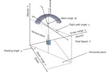
In Eq. 1, xi, yi, zi represent the position of the i-th parafoil, Vi represents the total speed, γi is the flight path angle, and φi is the heading angle, In Eq. 2, mi is the mass of the i-th parafoil, g is the acceleration due to gravity, Di is the resistance, L'i represents the combined lift force, and ϕ indicates the bank angle, which depends on the pull-down amount of the control ropes on the left and right sides of the parafoil’s trailing edge. By differentiating Eq. 1 and substituting Eq. 2 into it, the following second-order point-mass model for the parafoil can be derived:
Among them, represents the position vector of the i-th parafoil in the cluster, represents the velocity vector, and represents the equivalent control input vector of the i-th parafoil along the three axes of the inertial coordinate system. After obtaining the equivalent control vector ui(t), the bank angle of the parafoil system (Menon et al. 1999) can be calculated using the Eq. 4:
Problem description
During transportation tasks in a multi-parafoil formation, the special structure and complex environment of the parafoils make them vulnerable to atmospheric turbulence, which may cause the parafoil ropes to become entangled. Additionally, sudden encounters with birds may result in a parafoil failure, preventing it from completing the designated transportation task as originally planned. In view of the above-mentioned sudden failure situation, this paper mainly studies the cooperative task reconfiguration of multi-parafoil formation under failure conditions.
In response to failures caused by the above unexpected incidents, it is necessary to establish the following countermeasures for cooperative mission planning in multi-parafoil formations under failure conditions: determine the fault; assess whether the task reconstruction requirements are met; regroup the replacement parafoil formation; carry out formation flying; and prevent collisions between parafoils.
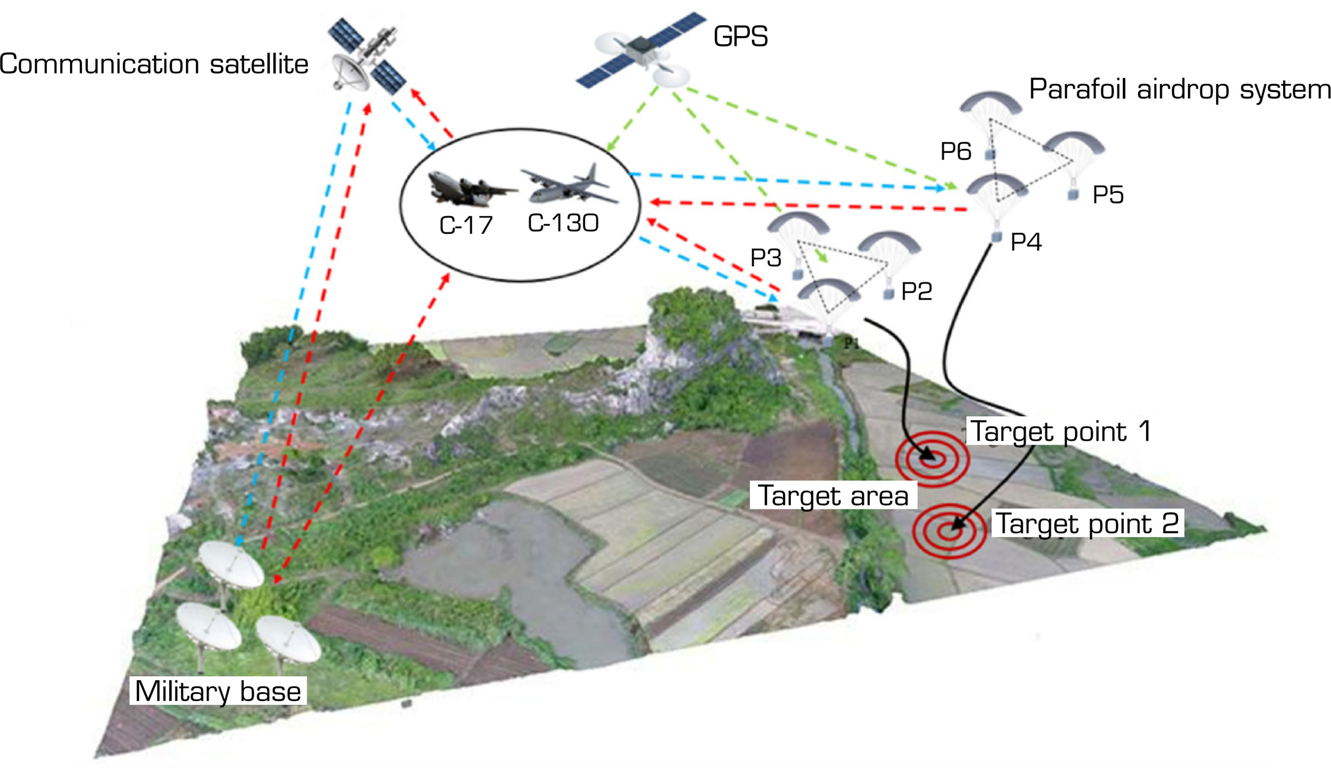
According to the requirements of the airdrop transportation mission for a multi-parafoil formation under fault conditions, a dynamic planning strategy for the cooperative mission of the multi-parafoil formation is proposed, as shown in Fig. 2.
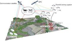
Schematic diagram of the cooperative mission planning principle of multi-parafoils formation.
The core idea is that when a parafoil fails, the task priority should first be determined first. The parafoil with a lower task priority will abandon its original target point and take over the high-priority transportation task of the faulty parafoil. The replacement parafoil will join the high-priority formation and reform the formation to continue flying. As shown in Fig. 2, P1-P3 represent parafoils 1 through 3, forming a high-priority task formation heading to target point 1, while P4-P6 represent parafoils 4 through 6, forming a low-priority task formation heading to target point 2. Assuming P3 fails at a certain altitude and cannot reach the predetermined target point, the task of P6 is modified, and the previous task heading to target point 2 is abandoned, with P3 replaced by P6 for target point 1.
Formation of cooperative task restructuring
Multi-parafoils formation cooperative task reconstruction
An event-triggering mechanism (Ge et al. 2020) is designed to monitor the real-time operating state of the parafoil. By calculating the relative distance between the parafoil and the center of the formation, it is determined whether this relative distance exceeds the safety threshold. If the relative distance exceeds the safety threshold, an event will be triggered.
Assuming that there are N parafoils in the formation, the position of each parafoil at time t is expressed as pi(t), and the center position of the parafoil formation is:
The relative distance di(t) between the i-th parafoil and the formation center is obtained by calculating the Euclidean distance:
namely:
The fault can be detected by setting a threshold value dth for the relative distance. At each sampling time tk, it is determined whether a fault occurs based on the following conditions:
where the triggering condition ρ = 1 indicates failure, and ρ = 0 indicates normal.
Calculation of the latest detachment time based on the gliding ratio
An event-triggering mechanism is designed to monitor the parafoil’s status in real-time for signs of failure. If a parafoil fails, a parafoil from the low-priority formation is transferred to replace it and complete the transportation task.
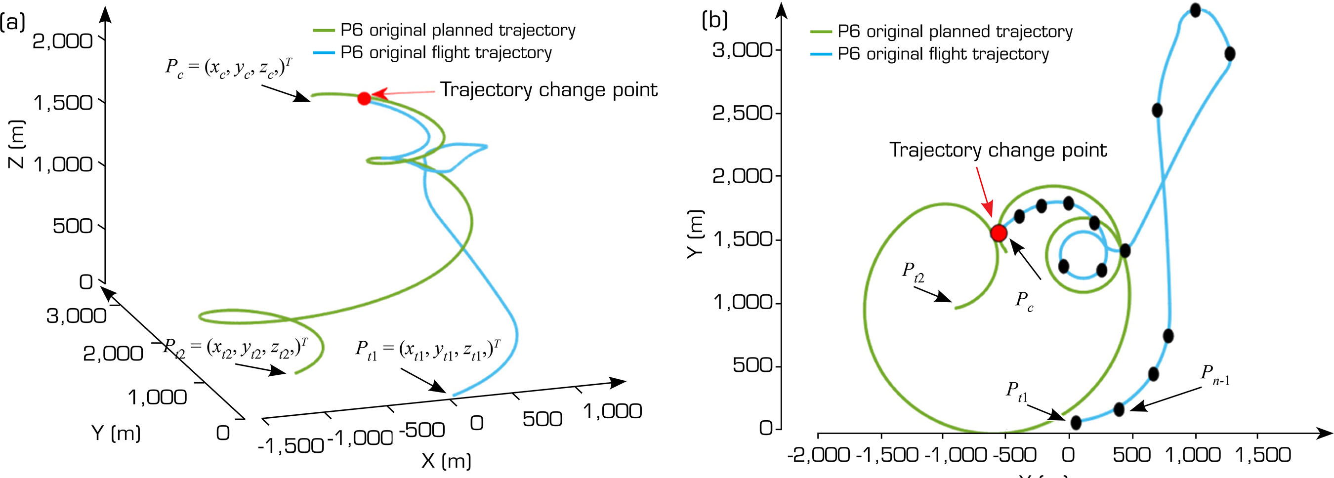
Due to the unique structure of the parafoil, there are many restrictions on its flight movement. After a failure, it is necessary to ensure that the parafoil has sufficient altitude to meet the latest detachment time requirements while adjusting its originally planned flight path. Otherwise, the parafoil will land before reaching the high-priority target point. In this paper, the latest detachment time is calculated based on the glide ratio (Ghapanvary et al. 2021). Figure 3 shows the parafoil trajectory diagram. As shown in Fig. 3a, assuming that the current position of the replacement parafoil is at , the originally planned target position is at . After the failure, the task target point is changed, and the parafoil proceeds to the new target point . Since the horizontal projection of the parafoil in actual flight is not a straight line but a curve, this curve can be divided into multiple path points, as shown in Fig. 3b, which can be approximated by multiple waypoints. The horizontal distance of the parafoil’s actual glide is calculated by accumulation.
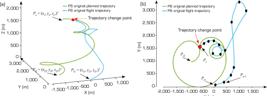
Trajectory diagram for calculating detachment time in case of failure. (a) 3D trajectory diagram for task replacement in case of failure; (b) 2D trajectory diagram for task replacement in case of failure.
The specific calculation is as follows:
In Eq. 9, the curve is approximated as segments of a straight line, and the waypoints of each straight line segment are denoted as , where , and .
To calculate the horizontal distance of the parafoil’s glide, the sum of the horizontal distances Lhorizontal is used, as expressed below:
The vertical distance between the parafoil and the target position is given by the difference between the coordinates zc and zt, as expressed below:
The horizontal glide distance Lglide can be calculated by multiplying the glide ratio k with the vertical distance hv, as expressed below:
where k represents the glide ratio of the parafoil and Lglide represents the horizontal glide distance achievable by the parafoil, calculated based on the glide ratio.
According to the requirements, for the parafoil to safely complete the airdrop task, the achievable horizontal distance of the parafoil must be greater than the actual required gliding distance, ensuring sufficient altitude to perform the flight maneuver:
Eq. 13 is equivalent to:
In Eq. 14, tdetach represents the detachment time at the parafoil’s current position and vmax represents the maximum speed of the parafoil.
To sum up, if the replacement parafoil leaves the original formation for a new target point before the latest detachment time, sufficient altitude can be guaranteed to change its flight path and land at the target point with high task priority.
Design of control law under fault conditions
By calculating the latest detachment time of the replacement parafoil and ensuring that it meets the formation reconstruction requirements, the control law (Thierry et al. 2022) is switched to ensure stably joining of the high-priority formation and following of the formation leader to safely reach the new target point.
Assuming that during the formation airdrop transportation, the i-th parafoil suddenly failed and could not continue to complete the airdrop task, the j-th parafoil is transferred to take over the high-priority airdrop task. The position and speed of the pilot parafoil in the high-priority formation are pleader1 and Vleader1. Therefore, it is necessary to design a control law so that the j-th parafoil can safely and stably join the new formation and proceed the new target point.
To complete the airdrop transportation task, the control law of the j-th parafoil is designed as follows:
where kp represents the position feedback gain and kv represents the velocity feedback gain.
To ensure that the j-th parafoil can stably reach the new target point pt1, Lyapunov function V (t) is constructed as follows:
To verify the stability of the control system, the position error part of the time derivative is calculated as follows:
The velocity error is part of the derivative :
Combined with Eq. 17 and 18, it is:
Simplify to:
Properly increasing the gain kp makes the first term show a negative feedback effect and does not influence the system, and if kv is a positive definite, is always negative or zero, that is:
Equation 21 shows that the derivative of the function Vt does not increase, and the energy of the system decreases monotonously or remains unchanged over time, so the system is stable (Kuang et al. 2024).
To sum up, by designing an effective control law, the replacement parafoil can fly stably and move to a new target point in case of failure.
Formation flying based on the leader-follow algorithm
The leader-follower algorithm (Z. Wang et al. 2023) is a common formation control algorithm, in which the pilot parafoil guides other parafoils to form a configuration based on specific rules. The leader parafoil is responsible for tracking the formation reference trajectory, and the other followers adjust their motion states according to the leader’s position and speed to create and maintain the formation shape. When a fault occurs, the control law of the replacement parafoil j is switched, and the PD control strategy is used to control the system behavior of the j-th parafoil through proportional and derivative terms, so that it can join the new formation and continue to fly with the pilot parafoil. The tracking velocity of the replacement parafoil in the next stage x, y, z direction is calculated as follows:
In Eq. 22, the proportional gain and differential gain are respectively k1 and k2 Dx, Dy, Dz are the position errors of the replacement parafoil and the leader parafoil of the high task priority formation in the direction of x, y, z, Vxleader1, Vyleader1 Vzleader1 represents the velocity component of the leader of the high task priority formation, and represents the current velocity component of the j-th replacement parafoil.
To ensure that the speed does not exceed the maximum limit and to prevent instability caused by excessive speed, the speed is proportionally limited. The total tracking speed is then calculated as follows:
If V2j(t) is greater than the maximum allowable speed Vmax, proportional speed limiting is performed as follows:
To prevent collisions between parafoils, when the distance between them is less than the safe distance R, the velocity vector of the parafoil in the new formation is adjusted as follows:
In the Eq. 25, Dx3, Dy3, Dz3 represents the Euclidean distance between the current parafoil and other parafoils in the direction x, y, z; ξ represents the repulsion term generated when the distance between parafoils is less than the safe distance; represents a distance scaling factor.
Eq. 24 limits the tracking speed relative to the leader, and this paper also limits the anti-collision speed in a similar manner. Once the safety velocity Vsafe is exceeded, where Vsafe is defined based on the safe distance between parafoils to prevent collision, the anti-collision speed is limited as follows:
The total anti-collision speed of the parafoil in the new formation is the average of the revised anti-collision speeds of each parafoil, as follows:
where N represents the number of parafoils in the new formation.
Therefore, the final total velocity vector of the j-th replacement parafoil is:
where k3 represents the velocity correction factor.
In the manuscript, the control input for each parafoil is defined as the time derivative of its velocity vector, representing the acceleration components along the three coordinate axes. This formulation explicitly links control actions to dynamic changes in velocity, providing a mechanism for directly regulating the parafoil’s motion. This ensures that formation maintenance and collision avoidance can be achieved through acceleration control. The mathematical expression of this control input is given in Eq. 4:
The stability analysis described in the Lyapunov-based stability analysis section is conducted based on this control law, which defines the control input as the time derivative of the velocity vector. The final control actuation of the parafoil is executed through the ropes connected to the left and right sides of its trailing edge. The roll angle obtained from Eq. 4 represents the required bank angle to achieve the desired flight trajectory. This roll angle directly affects the distribution of tension between the two control lines, thereby influencing the parafoil’s orientation and flight path. The control mechanism relies on differential actuation, where the difference in rope tensions determines the effective roll response.
LetTleft and Tright denote the tensions in the left and right ropes, respectively. The differential tension ΔT = Tleft - Tright is related to the roll angle ϕi through a proportional relationship, ΔT = k·ϕi, where k is a constant dependent on the parafoil’s geometry and control sensitivity. The individual tensions can be expressed as and , with Tbase being the baseline tension when the parafoil is in neutral flight. By dynamically adjusting these tensions according to the control algorithm, the desired roll angle can be achieved and maintained, ensuring accurate trajectory tracking. These formulations for ΔT, Tleft, and Trigt are developed by the authors based on the control mechanism of the parafoil system.
Simulation and analysis
To validate the effectiveness of the proposed algorithm, simulations were conducted using MATLAB 2020. The simulation parameters were set as follows: simulation time sim_time = 500 s, time step dt = 0.1 s. There are two formations in total, each consisting of three parafoils. Table 1 provides the initial position data for these parafoils, flight speed Vmax = 32 m·s-1, Vmin = 18 m·s-1, heading angle φmax = 𝜋 rad, φmin = −𝜋 rad, flight path angle γmax = −8 × 𝜋 180 rad, = γmin −16 × 𝜋 180 rad, repulsion term ξ = 200, distance scaling factor μ = 13.5, distance threshold dth = 80 m, k1 = 0.4, k2 = 0.5, k3 = 0.5, Vsafe = 25 m·s-1.
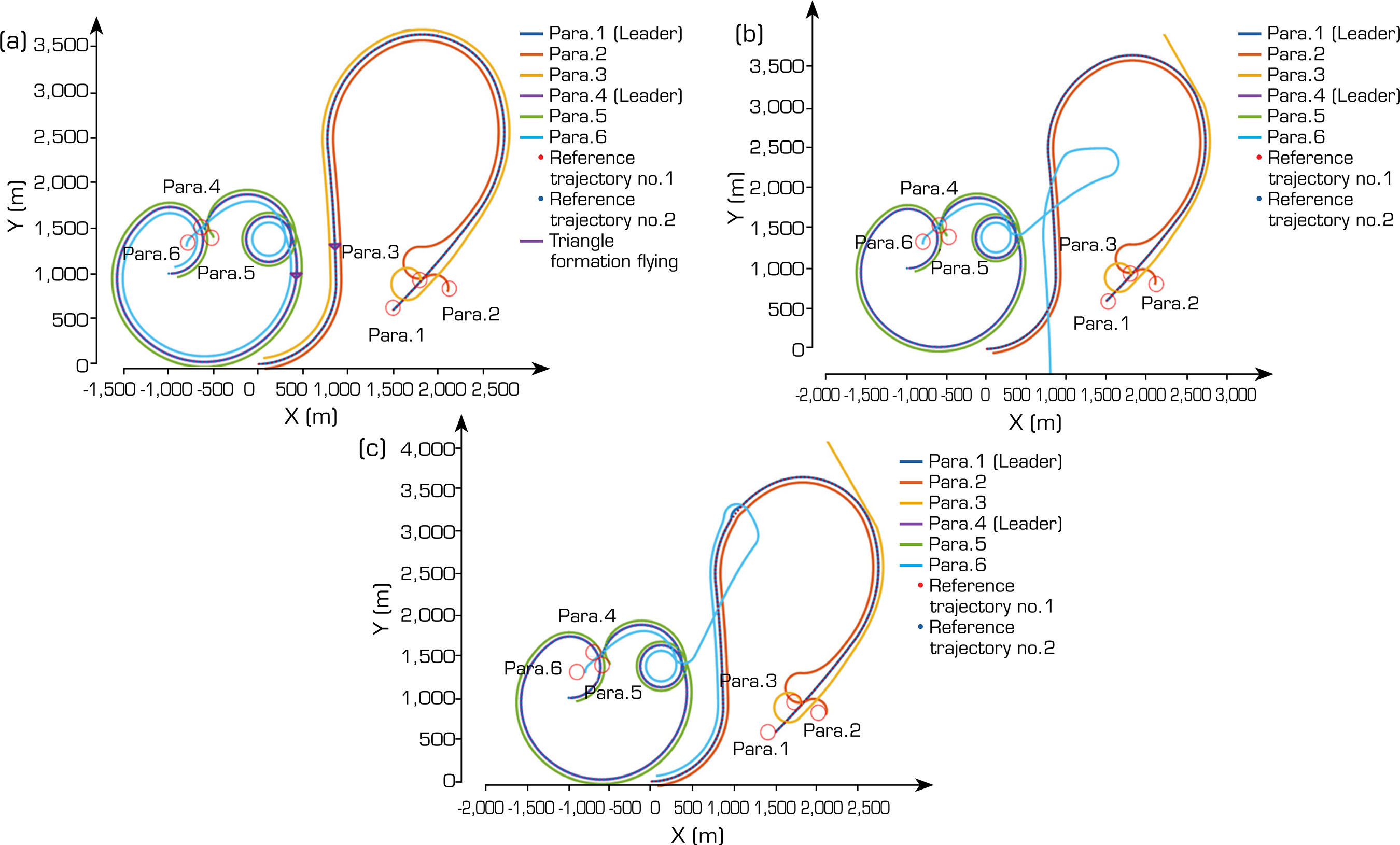
Figure 4 shows the two-dimensional trajectories of the multi-parafoil cluster formation during a cooperative task flight. Figure 4a shows the scenario where no parafoil fails during flight, and the two groups of parafoils form a stable formation to complete the transportation task. Figure 4b shows the process of a multi-parafoil formation collaborative transportation task. The event-trigger mechanism detects that the P3 parafoil in the high-priority formation fails to complete the transportation task due to a sudden situation, as shown by the yellow line in the figure. The P6 parafoil needs to be transferred from the low-priority formation to replace the P3 parafoil to complete the task, as shown by the blue line in the figure. At this time, the latest detachment time is calculated based on the current position of the P6 parafoil to determine whether its current height meets the requirements of the replacement task. After the calculation, the P6 parafoil does not meet the latest detachment time requirement due to insufficient height and cannot complete the replacement task or reach the high-priority target point. Figure 4c shows that the P6 parafoil meets the latest detachment time requirement and has sufficient altitude to complete task redistribution. Therefore, the control law of the P6 parafoil is adjusted to enable it to stably integrate into the high-priority formation, as shown by the blue line in the figure. At the same time, the leader-follower algorithm and PD control strategy are adopted to enable it to form a new formation with the high-priority group and reach the target point safely and stably.
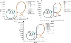
2D trajectories diagram of multi-parafoil formation flight. (a) Failure-free formation task coordination; (b) If a fault occurs but the detachment time is not met, the replacement task fails; (c) If a fault occurs but the detachment time condition is met, the replacement task is successful.
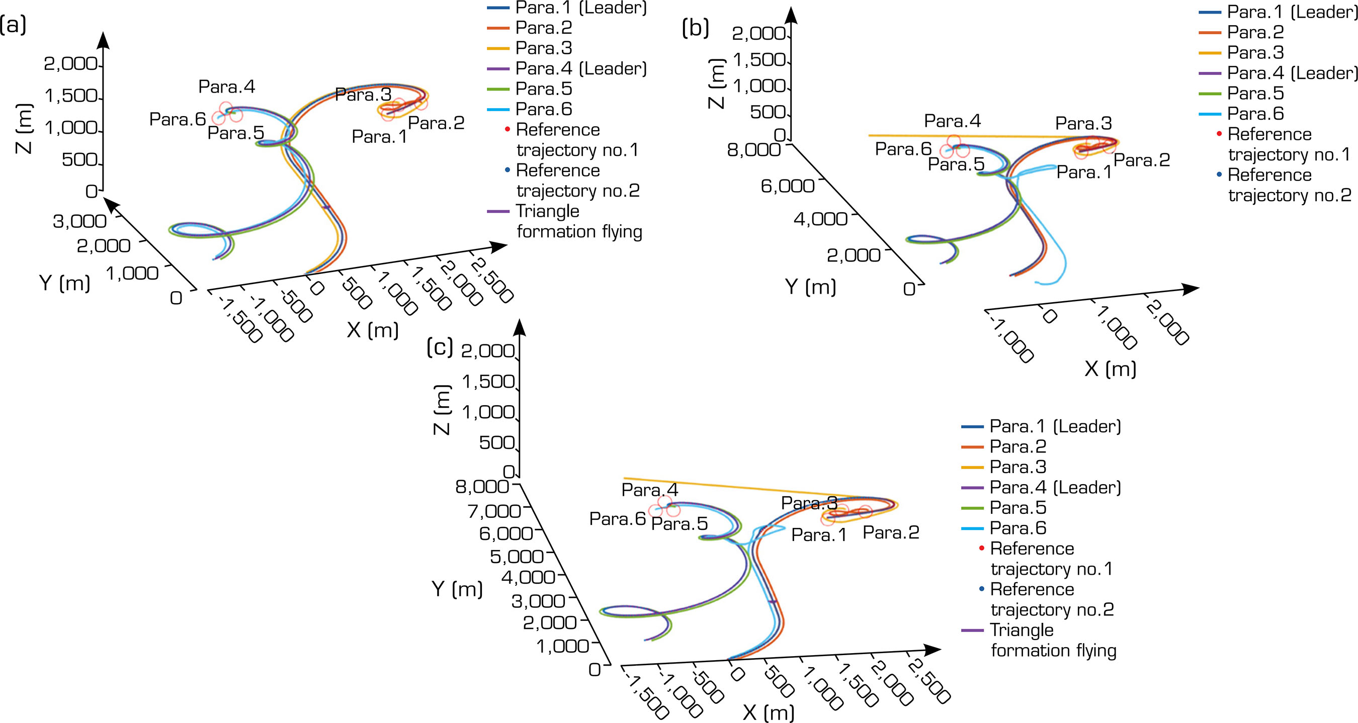
Figure 5 is a three-dimensional trajectory diagram of the parafoil formation collaborative task flight. Figure 5b shows that the P6 parafoil cannot complete the replacement mission due to insufficient altitude, as shown by the blue line.
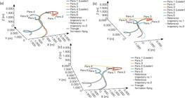
3D trajectories diagram of multi-parafoil formation flight. (a) Failure-free formation task coordination; (b) If a fault occurs but the detachment time is not met, the replacement task fails; (c) If a fault occurs but the detachment time condition is met, the replacement task is successful.
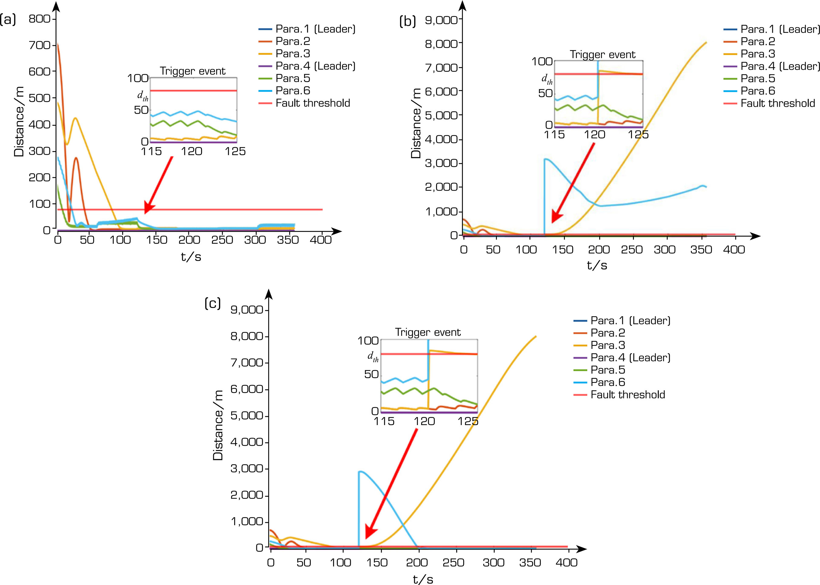
Figure 6 shows the position error, which is described in Eq. 7, between parafoils in the formation during flight. Figure 6a shows that under fault-free conditions, there is an initial distance error between parafoils because the formation has not been established in the initial stage. However, as the formation gradually stabilizes, the distance difference between parafoils gradually decreases, and no event is triggered until the end of the mission. As shown in Figure 6b, at a certain moment, the distance between the P3 parafoil and the formation exceeds the safety threshold, resulting in an event trigger, which is judged to be a fault, as shown by the yellow line in the figure. The P6 replacement parafoil fails to meet the latest detachment time requirement due to insufficient height and cannot complete the transportation task, resulting in a large distance error between P6 and other parafoils in the high-priority formation, as shown by the blue line in the figure. As shown in Fig. 6c, the P6 replacement parafoil meets the latest detachment time requirement. By switching the control law of the P6 parafoil, it can stably join the high-priority-task formation, where the leader-follower algorithm is used for formation flight. Therefore, before joining the high-priority-task formation, there is a large error between the P6 parafoil and other parafoils, and after joining the high-priority-task formation, the error gradually decreases, as shown by the blue line in the figure.
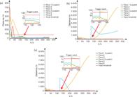
Position error during the multi-parafoil formation flight. (a) Failure-free formation task coordination; (b) If a fault occurs but the detachment time is not met, the replacement task fails; (c) If a fault occurs but the detachment time condition is met, the replacement task is successful.
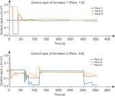
To provide a clearer representation of the control performance, Fig. 7 depicts the magnitude of the control input ui for each parafoil. As shown, the distribution of control inputs reflects the designed coordination mechanism, ensuring that the formation maintains both stability and safety while effectively achieving the desired trajectory.
CONCLUSION
This paper proposes a cooperative task reconfiguration algorithm for multi-parafoil cluster formations. First, an event-trigger mechanism is designed to monitor the operational state of each parafoil within a time-stepping simulation framework. If a parafoil in the high-priority formation fails, one from the low-priority formation is selected to replace it and complete the transportation task. Secondly, it is necessary to determine whether the formation reconfiguration conditions are met before transferring. Therefore, according to the gliding ratio, the latest detachment time by which the parafoil must leave the original formation is calculated, and it is determined whether the current altitude meets the task reconfiguration requirements. If so, the control law for the replacement parafoil is designed and switched to ensure that it gradually approaches the leader parafoil in the new formation. Finally, the leader-follower algorithm combined with the PD control strategy is used to guide the parafoil to join the new formation and achieve formation flight. This method lays a solid theoretical foundation for airdrop transportation in multi-parafoil cluster formations and effectively addresses the problem of formation task reconstruction in the event of unexpected failures during airdrop transportation. It comprehensively improves the reliability and safety of the airdrop transportation task of a multi-parafoil cluster formation.
ACKNOWLEDGMENTS
Not applicable.
-
Peer Review History
Single Blind Peer Review.
-
DECLARATION OF USE OF ARTIFICIAL INTELLIGENCE TOOLS
AI tools were used only to assist with language polishing and translation during the preparation of this manuscript. All scientific content, including the research design, data analysis, results, and conclusions, was created entirely by the authors.
-
FUNDING
Not applicable.
DATA AVAILABILITY STATEMENT
All data sets were generated or analyzed in the current study.
REFERENCES
-
Ali RM, Khashayar K (2016) Constrained distributed cooperative synchronization and reconfigurable control of heterogeneous networked Euler-Lagrange multi-agent systems. Inf Sci 370:578.597. https://doi.org/10.1016/j.ins.2015.09.032
» https://doi.org/10.1016/j.ins.2015.09.032 -
Chen Q, Sun Y, Zhao M, Liu M (2021) Consensus-based cooperative formation guidance strategy for multiparafoil airdrop systems. IEEE Trans Autom Sci Eng 18:2175-2184. https://doi.org/10.1109/TASE.2020.3020558
» https://doi.org/10.1109/TASE.2020.3020558 - Chen Q, Zhao M, Zhao Z, Ma M, Huang R (2016) Multiple autonomous parafols system modeling and rendezvous control. Acta Aeronaut Astron Sin 37:3121-3130.
-
Ge X, Qing-Long H, Lei D, Yu-Long W, Xian-Ming Z (2020) Dynamic event-triggered distributed coordination control and its applications: a survey of trends and techniques. IEEE Trans Syst Man Cybern Syst 50:3112-3125. https://doi.org/10.1109/TSMC.2020.3010825
» https://doi.org/10.1109/TSMC.2020.3010825 -
Ghapanvary MA, Nosratollahi M, Karimi J (2021) Dynamic response analysis of a high glide ratio parachute system. Int J Eng 34(1):195-201. https://doi.org/10.5829/ije.2021.34.01a.22
» https://doi.org/10.5829/ije.2021.34.01a.22 -
Guo Z, Chen G (2022) Fully distributed optimal position control of networked uncertain Euler-Lagrange systems under unbalance digraphs. IEEE Trans Cybern 52:10592-10603. https://doi.org/10.1109/TCYB.2021.3063619
» https://doi.org/10.1109/TCYB.2021.3063619 -
Kuang Z, Guo Y, Deng X (2024) Research on task offloading and resource allocation in edge computing network of RIS-assisted UAV based on Lyapunov. J Commun 45:258-273. https://doi.org/10.11959/j.issn.1000-436x.2024155
» https://doi.org/10.11959/j.issn.1000-436x.2024155 -
Li YH, Zhao M, Yao M, Chen Q, Guo R, Sun T, Jiang T, Zhao Z (2020) 6-DoF modeling and 3D trajectory tracking control of a powered parafoil system. IEEE Access 8:151087-151105. https://doi.org/10.1109/ACCESS.2020.3016669
» https://doi.org/10.1109/ACCESS.2020.3016669 -
Luca C, Fabio M, Domenico P, Mario T (2008) Leader-follower formation control of nonholonomic mobile robots with input constraints. Automatica 44:1344-1349. https://doi.org/10.1016/j.automatica.2007.09.019
» https://doi.org/10.1016/j.automatica.2007.09.019 -
Menon PK, Sweriduck GD, Sridhar B (1999) Optimal strategies for free-flight air traffic conflict resolution. J Guid Control Dyn 22:202-211. https://doi.org/10.2514/2.4384
» https://doi.org/10.2514/2.4384 -
Philip D, Hattis BD, Appleby T, Fill J (1997) Precision guided airdrop system flight test results. Am Inst Aeronaut Astronaut 97:158-168. https://doi.org/10.2514/6.1997-1468
» https://doi.org/10.2514/6.1997-1468 -
Pini G, Sharoni F, Moran F (2010) Coordination and communication of cooperative parafoils for humanitarian aid. IEEE Trans Aerosp Electron Syst 46:1747-1761. https://doi.org/10.1109/TAES.2010.5595592
» https://doi.org/10.1109/TAES.2010.5595592 -
Prakash O, Ananthkrishnan N (2006) Modeling and simulation of 9-DOF parafoil-payload system flight dynamics. Am Inst Aeronaut Astronaut 1-16. https://doi.org/10.2514/6.2006-6130
» https://doi.org/10.2514/6.2006-6130 -
Qian N, Tao G, Chen B, Lei Y, Zhao C (2019) Multi-UAVs trajectory and mission cooperative planning based on the Markov model. Phys Commun 35:1-10. https://doi.org/10.1016/j.phycom.2019.100717
» https://doi.org/10.1016/j.phycom.2019.100717 -
Rosich A, Gurfil P (2012) Coupling in-flight trajectory planning and flocking for multiple autonomous parafoils. Proc Inst Mech Eng G J Aerosp Eng 226:691-720. https://doi.org/10.1177/0954410011413637
» https://doi.org/10.1177/0954410011413637 -
Ruixuan W, Zichen W (2021) Study on task allocation of UAV swarm based on cognitive control. J Syst Simul 33:1574-1581. https://doi.org/10.16182/j.issn1004731x.joss.20-0213
» https://doi.org/10.16182/j.issn1004731x.joss.20-0213 -
Su M, Cheng Y, Hu J, Zhao C, Jia C, Xu Z, Zhang JF (2021) Combined optimization of swarm task allocation and path planning based on improved ant colony algorithm. Unmanned Syst Technol 4:40-50. https://qikan.cqvip.com/Qikan/Article/Detail?id=7105552068
» https://qikan.cqvip.com/Qikan/Article/Detail?id=7105552068 -
Sun Q, Yang J, Sun H, Chen Z (2024) Review of key technology for autonomous homing of parafoil systems. J Natl Univ Def Technol 46:578-597. https://doi.org/10.11887/j.cn.202404001
» https://doi.org/10.11887/j.cn.202404001 -
Thierry LM, Gilles F, Clément T (2022) Simulation and comparison of control laws for the landing of an autonomous parafoil under adverse conditions. AIAA 26 https://doi.org/10.2514/6.2022-2731
» https://doi.org/10.2514/6.2022-2731 -
Wang P, Xiaowen S, Peiyuan L (2023) Formation reconfiguration collision avoidance control for multiple UAVs based on artificial potential field method. Unmanned Syst Technol 6. https://doi.org/10.19942/j.issn.2096-5915.2023.05.51
» https://doi.org/10.19942/j.issn.2096-5915.2023.05.51 - Wang Z, Liu K, Guo J, Liu X (2023) A multi-UAVs and multi-USVs formation cooperative mechanism based on leader-follower strategy. Acta Aeronaut Astronaut Sin 11:729791-2-729791-16.
-
Zhang J, Chen Y, Yang Q, Lu Y, Shi G, Wang S, Hu J (2022) Dynamic task allocation of multiple UAVs based on improved A-QCDPSo. Electronics 11:2-17. https://doi.org/10.3390/electronics11071028
» https://doi.org/10.3390/electronics11071028
Edited by
-
Section editor:
Luiz Martins-Filho https://orcid.org/0000-0002-7287-5979

 Source: Elaborated by the authors.
 Source: Elaborated by the authors.
 Source: Elaborated by the authors.
 Source: Elaborated by the authors.
 Source: Elaborated by the authors.
 Source: Elaborated by the authors.
 Source: Elaborated by the authors