Frequency-Tunable Antenna Using IFA-to-Loop Mode Switching for Compact Wireless Devices
Abstract
This paper introduces a new approach to reconfiguring an antenna’s operating frequencies by switching between an inverted-F antenna (IFA) mode and a loop mode. This frequency agility is achieved by incorporating a switch at the end of the antenna trace, which connects or disconnects the trace from the antenna ground, thereby altering the antenna's resonant behavior depending on the selected mode. To validate the concept, a prototype antenna was fabricated, and the measured results showed strong alignment with simulation predictions. In the IFA mode, the antenna exhibits two resonant frequencies around 1 GHz and 2 GHz, while in the loop mode, it achieves two close resonances approximately at 1.4 GHz and 1.7 GHz. This ability to switch between modes and cover multiple frequency bands makes the proposed design particularly well-suited for LTE-enabled mobile devices that demand wide or multi-band operation.
Index Terms
Frequency tuning; Inverted-F Antenna; Loop Antenna; LTE
I. Introduction
The rapid growth of data-intensive wireless services has intensified the need for compact antennas capable of supporting multiple bands and adaptive operation within the strict size, weight, and cost constraints of mobile devices [1]. Among internal antenna candidates, the inverted-F antenna (IFA) remains particularly attractive owing to its low profile, compact footprint, and structural versatility [2]. Multi-band IFAs are commonly realized using multiple radiating branches [3], while alternative techniques include parasitic loading [4], [5], integrated LC resonators, twisted conductors [6], and ground-plane modification to excite additional resonant modes [7]. Loop antennas are also widely employed in smartphones, often implemented through the metallic frame. Although loops inherently exhibit multimode behavior, their modal spacing is typically too large for applications requiring closely spaced operating bands [8].
To enhance tuning flexibility and impedance control, lumped-element loading has been widely investigated [9],[10],[11],[12]. Capacitive loading along the radiating strip of planar IFAs enables resonance reduction [9], while lumped series resonators have produced dual-band responses at 2.45 and 5.8 GHz, albeit with a large frequency ratio [10]. Frequency tuning using varactor diodes in slot antennas has also been demonstrated [11], and shunt capacitors have been used to improve high-band matching, though again with widely separated resonances [12].
As wireless communication platforms continue to converge, antennas with multifunctional and adaptive capabilities are increasingly essential. Reconfigurable antennas have therefore attracted strong interest for integrating multiple radio services within a single compact radiator [13]. Their adaptability is typically achieved through electrical, mechanical, or material-based tuning mechanisms that dynamically modify antenna characteristics [14]. Common reconfiguration modes include frequency, radiation pattern, and polarization control [15], [16], with some designs enabling simultaneous multi-parameter tuning [17], [18].
Recent studies have largely focused on narrowband-tunable antennas across various topologies, including dipole, IFA, loop, and patch structures [19],[20],[21]. To reduce RF front-end complexity in cognitive-radio systems, several designs have combined wideband and switchable narrowband responses within a single radiator. For instance, the monopole in [22] transitions between UWB and multiple narrowband states using a switchable matching network, while the Vivaldi antenna in [23] achieves wideband operation and discrete narrowband modes through PIN-diode-controlled resonators embedded in the feed. Despite their effectiveness, such approaches increase hardware complexity because the number of switches and bias circuits scales with the number of operating states. These additions elevate cost and design effort, limiting their suitability for compact, low-complexity wireless platforms.
To address this challenge, this paper introduces a simple structural modification that enables frequency reconfiguration in an IFA. By placing a switching element near the open end, the antenna can transition between IFA and loop modes, providing controllable resonant behavior and extended bandwidth coverage. Section II describes the antenna design and simulated characteristics, Section III presents fabrication and measurement results, Section IV compares the design with related reconfigurable antennas, and Section V concludes the work.
II. Reconfigurable Antenna Design
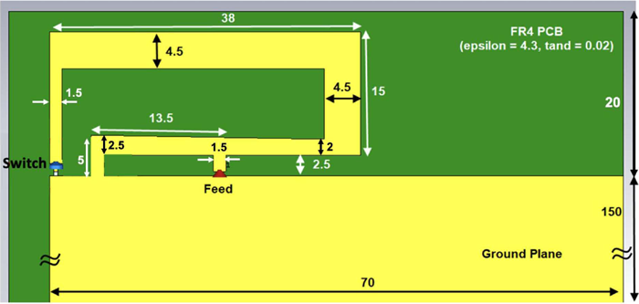
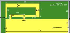
As illustrated in Fig. 1, the proposed meandered IFA comprises a feeding port, a shorting arm, and a radiating arm. To implement the reconfigurable operation, a grounding switch is integrated at the tip of the open-ended arm, allowing the antenna to switch between IFA mode and loop mode. When the switch is turned off, the antenna functions in the conventional IFA mode; when the switch is turned on, the antenna operates as a loop antenna. The detailed dimensions of the antenna structure are indicated in Fig. 1. The antenna is designed on an FR4 substrate with a thickness of 0.8 mm and a relative dielectric constant (εr) of 4.3. Design and optimization of the antenna were carried out in CST Microwave Studio, version 2021.
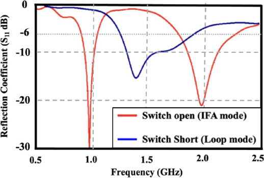
The simulated reflection coefficients of the proposed antenna in both IFA mode (switch off) and loop mode (switch on) are depicted in Fig. 2. In the IFA mode, the antenna achieves dual resonances at approximately 1 GHz and 2 GHz. When the switch is activated, shifting the antenna to loop mode, two close resonances appear at around 1.4 GHz and 1.7 GHz. By leveraging both modes, the antenna successfully covers a broad frequency range, maintaining a return loss better than 6 dB across the 850–1050 MHz and 1.25–2.25 GHz bands. These bands encompass several cellular, navigation, and short-range wireless services, including sub-GHz LTE/UMTS systems and mid-band cellular, GNSS, and ISM-band applications, demonstrating the suitability of the proposed antenna for multi-standard wireless devices.
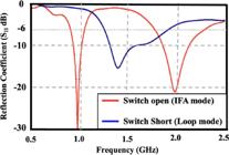
Simulated reflection coefficient (dB) of the proposed antenna for IFA and Loop antenna modes.
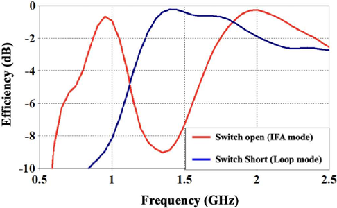
The simulated total efficiency of the proposed antenna operating in both modes—IFA mode (with the switch in the OFF state) and loop mode (with the switch ON)—is illustrated in Fig. 3. The results demonstrate that the antenna maintains a total efficiency above –2 dB across both operating bands, specifically 850–1050 MHz and 1.25–2.25 GHz, by switching between the two configurations.
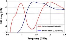
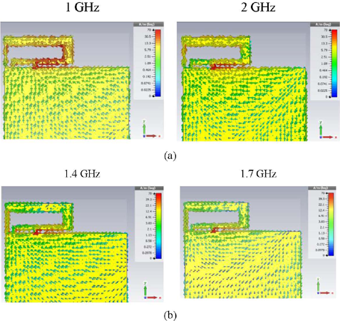
Fig. 4 presents the surface current distributions at the resonance frequencies corresponding to each mode. In the IFA mode, shown in Fig. 4(a), the current distribution at the fundamental resonance of 1 GHz displays strong current concentrations near the feed point and minimal currents at the antenna tip (i.e., at the switch location), consistent with the quarter-wavelength behavior typical of an IFA. At 2 GHz, a second-order mode emerges, characterized by a current null at the midpoint of the IFA arm. In contrast, Fig. 4(b) highlights the loop mode operation. When the switch is ON, significant current flows through it, activating a loop configuration that resonates at frequencies near one wavelength relative to the loop’s perimeter.
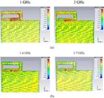
Surface current the proposed antenna at the resonance frequencies (a) IFA mode (b) Loop mode.
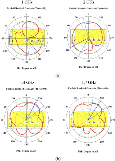
The corresponding far-field radiation patterns at the resonance frequencies are depicted in Fig. 5. In IFA mode at 1 GHz, the antenna exhibits a more directional pattern toward the ground plane. At 2 GHz, the pattern becomes more omnidirectional. Meanwhile, the loop mode presents radiation patterns oriented in the opposite direction, reflecting the altered current distribution and mode structure of the antenna at its respective resonant frequencies. The observed radiation characteristics provide insight into the suitability of the proposed antenna for practical handheld and embedded wireless devices. In the IFA configuration, the stronger radiation toward the ground plane at the lower resonance supports efficient coupling with the device chassis, which is beneficial for sub-GHz cellular links where coverage and body interaction are critical. At higher frequencies, the more omnidirectional behavior improves link reliability in multipath environments typical of urban and indoor scenarios. When operating in loop mode, the reversed radiation orientation indicates a different current path and effective radiator length, enabling complementary spatial coverage. This dual radiation behavior enhances pattern diversity and can improve overall link robustness, making the antenna appropriate for compact multimode wireless platforms.
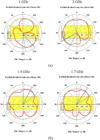
Azimuth plane realized gain radiation pattern the proposed antenna at the resonance frequencies (a) IFA mode (b) Loop mode.
III. Fabricated Prototype and Measured Results
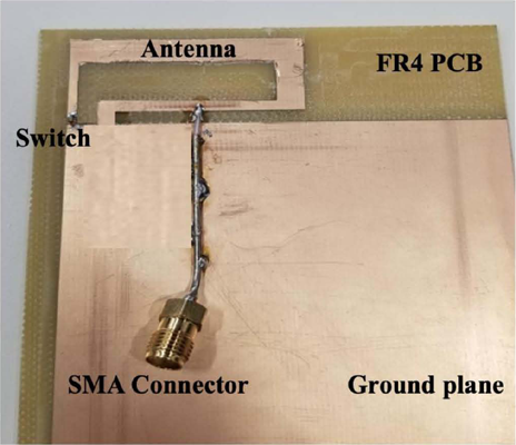
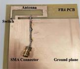
To verify the simulation results, a prototype of the proposed antenna was fabricated and experimentally tested. The fabricated prototype is presented in Fig. 6. As illustrated, a pigtail cable is employed to feed the antenna, with its ground soldered to the antenna’s ground plane to minimize any undesired radiation from the feed. In the fabricated prototype, the switching function was implemented manually rather than through an electronic switching circuit. The antenna tip was connected or disconnected using copper tape to emulate the two operating states of the design. This approach was adopted to experimentally validate the proposed operating principle while avoiding the additional complexity and potential parasitic effects associated with active switching components and biasing networks. The results therefore demonstrate the intrinsic performance of the antenna structure in each configuration. A practical implementation of the proposed reconfigurable structure can be achieved using RF PIN diodes as switching elements. However, it is important to note that the inclusion of PIN diodes in the RF path introduces additional insertion loss due to their finite series resistance in the ON state and parasitic capacitance in the OFF state. These non-ideal characteristics may slightly degrade the overall antenna efficiency, gain, and matching performance compared to the ideal case. Furthermore, the biasing network required for diode operation can introduce additional losses and potential disturbances to the RF current distribution if not carefully designed. Nevertheless, by selecting low-loss PIN diodes, optimizing the biasing circuit, and properly isolating the RF and DC paths (e.g., using RF chokes and DC blocking capacitors), the impact of these losses can be minimized, ensuring that the proposed design maintains acceptable performance in practical implementations.
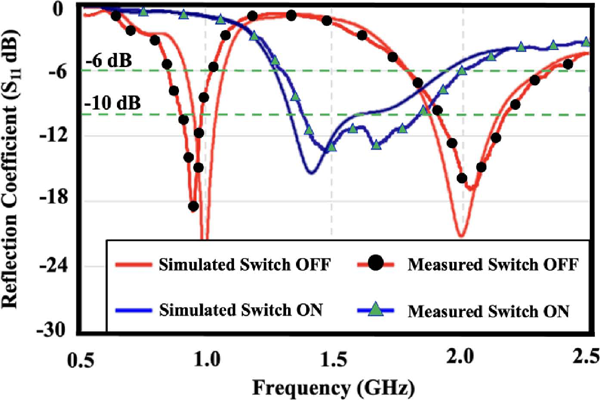
The simulated and measured reflection coefficient is depicted in Fig. 7, demonstrating good agreement between the simulated and measured results. In the IFA mode, the antenna exhibits two resonance frequencies around 1 GHz and 2 GHz, with corresponding operating bandwidths, with return loss better than 6 dB, of approximately 200 MHz and 500 MHz, respectively. In contrast, when operating in loop mode, the antenna achieves two resonance frequencies at approximately 1.5 GHz, and 1.7 GHz, effectively covering the frequency bands of 1.3–2 GHz. Table I summaries the simulated and measured (–6 dB and –10 dB) impedance bandwidth of the proposed antenna for the two different IFA nd loop modes that indicates a great agreement between the simulations and measurments. Minor discrepancies between the simulated and measured resonance frequencies can be attributed to fabrication and measurements tolerances as well as the influence of the pigtail feed. The −6 dB reflection coefficient level may be adopted as a practical benchmark to define the antenna impedance bandwidth. Although a −10 dB level is often used as a conventional reference, the −6 dB criterion is more suitable for compact, multi-band antennas operating in space-constrained environments such as mobile devices. At this level, 75% of the input power is still effectively transferred to the antenna, which is sufficient to maintain reliable radiation performance. In addition, modern RF front-end architectures typically include impedance tuning, matching networks, and adaptive power control, which help compensate for moderate mismatch levels. Therefore, using the −6 dB threshold provides a realistic and application-driven evaluation of the antenna performance, particularly in designs where achieving wideband or multi-standard coverage is prioritized over stringent matching at individual frequency bands.
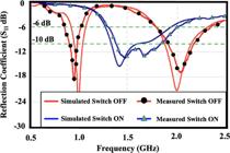
Simulated and measured reflection coefficient of the proposed antenna for different switch cases.
IV. State-of-the-Art Comparison
To assess the performance of the proposed frequency-reconfigurable antenna, a comparative study with recently reported designs is summarized in Table II. The comparison considers key practical parameters such as antenna topology, physical footprint, switching strategy and component count, achievable impedance bandwidth, and relevance to real device integration. The results indicate that the proposed structure maintains a compact form factor and limited ground-plane intrusion while providing noticeably wider impedance coverage than many contemporary solutions. In contrast to approaches that employ multiple PIN diodes or varactor-based tuning—methods that often increase circuit complexity, introduce additional losses, and may reduce radiation efficiency—the proposed antenna achieves frequency agility through a structural transition between IFA and loop modes. This operating principle removes the need for complex matching circuitry or numerous active components, thereby limiting parasitic effects, lowering implementation complexity, and simplifying fabrication. Overall, the comparison demonstrates that the proposed antenna achieves a favorable balance between compactness, bandwidth performance, and implementation simplicity, making it well suited for integration into space-constrained wireless devices requiring multi-band coverage.
Comparison of proposed antenna Performance with recent frequency reconfigurable antenna designs
V. Conclusion
In this study, a straightforward yet efficient approach has been introduced to transform a dual-band IFA into a wide-band loop antenna by incorporating a switch at the end of the IFA arm. The proposed antenna was designed, fabricated, and experimentally validated. The results demonstrate that the IFA and loop configurations exhibit distinct resonance frequencies, and by toggling between these two modes, the antenna achieves a broad operational bandwidth. Owing to its simplicity, compact size, and ease of implementation, the proposed method offers a promising solution for realizing multi-band antennas with small frequency ratios, making it well-suited for integration into smartphones and other compact mobile devices.
Data Availability Statement
All data generated or analysed during this study are included in this published article.
REFERENCES
- 1 T. Houret, L. Lizzi, F. Ferrero, C. Danchesi and S. Boudaud, "DTC-enabled frequency-tunable inverted-F antenna for IoT applications," IEEE Antennas and Wireless Propagation Letters, vol. 19, no. 2, pp. 307-311, 2020.
- 2 Z. Ying, “Antennas in cellular phones for mobile communications,” IEEE Proceedings, vol. 100, no. 7, pp. 2286–2296, 2012.
- 3 Z. D. Liu, P. S. Hall, and D. Wake, “Dual-frequency planar inverted-F antenna,”IEEE Transactions on Antennas and Propagation, vol. 45, no. 10, pp. 1451–1458, 1997.
- 4 J. Anguera, I. Sanz, J. Mumbru, and C. Puente, “Multiband handset antenna with a parallel excitation of PIFA and slot radiators,” IEEE Transactions on Antennas Propagation, vol. 58, no. 2, pp. 348–356, 2010.
- 5 L. Shi and Y. Wang, “An innovative parallel feeding approach to eliminate radiation efficiency local minimum in inverted-F antennas with the parasitic branch for metal-bezel smartphones,” IEEE Transactions on Vehicular Technology, vol. 74, no. 8, pp. 12703-12713, 2025.
- 6 J.-H. Kim, W.-W. Cho, and W.-S. Park, “A small dual-band inverted-F antenna with a twisted line,”IEEE Antennas and Wireless Propagation Letters, vol. 8, pp. 307–310, 2009.
- 7 Z. Bao, Y. X. Guo, and R. Mittra, “Single-layer dual-/tri-band inverted-F antennas for conformal capsule type of applications,”IEEE Transactions on Antennas and Propagation, vol. 65, no. 12, pp. 7257–7265, 2017.
- 8 A. H. Abdelgwad and M. Ali, “Isolation improvement between closely spaced antennas using EBG,” International Applied Computational Electromagnetics Society (ACES) Symposium, Monterey, USA, pp. 1–2, 2020.
- 9 K.-L. Wong and Z.-G. Liao, “Passive reconfigurable triple-wideband antenna for LTE tablet computer,”IEEE Transactions on Antennas and Propagation, vol. 63, no. 3, pp. 901–908, 2015.
- 10 J. H. Kim and C.-H. Ahn, “Small dual-band inverted-F antenna using series resonator,”Microwave and Optical Technology Letters, vol. 59, no. 7, pp. 1489–1493, 2017.
- 11 A. H. Abdelgwad and M. Ali, “Smartphone metal-casing integrated frequency-reconfigurable MIMO slot antenna,”International Journal of RF and Microwave Computer-Aided Engineering, vol. 32, no. 11, pp. 1–9, 2022.
- 12 Y. Liu, X. Yang, J. He, and Y. Ma, “Miniaturization of dual band PIFA for wireless LAN communication,”ETRI Journal, vol. 35, no. 3, pp. 530–533, 2013.
- 13 A. H. Abdelgwad and M. Ali, “Beam steering MIMO antenna for mobile handsets,” 15th European Conference on Antennas and Propagation (EuCAP), Düsseldorf, Germany, pp. 1–2, 2021.
- 14 S. Genovesi, A. D. Candia, and A. Monorchio, “Compact and low profile frequency agile antenna for multistandard wireless communication systems,”IEEE Transactions on Antennas and Propagation, vol. 62, no. 3, pp. 1019–1026, 2014.
- 15 A. H. Abdelgwad,MIMO antenna systems for wireless handheld devices, Ph.D. dissertation, University of South Carolina, Columbia, SC, USA, 2022.
- 16 Z. Chen, W. Hu, K. Wei, L. Wen, Z. Hu, and S. Gao, “A wideband polarization-reconfigurable antenna using the combined characteristic modes and common/differential modes,”IEEE Antennas and Wireless Propagation Letters, vol. 23, no. 3, pp. 1139–1143, 2024.
- 17 S.-T. Wang and L. Zhu, “A compact multifunctional antenna with frequency tunability and full-polarization reconfigurability,”IEEE Antennas and Wireless Propagation Letters, vol. 23, no. 11, pp. 3466–3470, 2024.
- 18 A. H. Abdelgwad and M. Ali, “Frequency/pattern reconfigurable printed monopole MIMO antenna for handheld devices,” 15th European Conference on Antennas and Propagation (EuCAP), Düsseldorf, Germany, pp. 1–4, 2021.
- 19 S. V. Hum and H. Y. Xiong, “Analysis and design of a differentially-fed frequency agile microstrip patch antenna,”IEEE Transactions on Antennas and Propagation, vol. 58, no. 10, pp. 3122–3130, 2010.
- 20 P.-Y. Qin, A. R. Weily, Y. J. Guo, T. S. Bird, and C. H. Liang, “Frequency reconfigurable quasi-Yagi folded dipole antenna,”IEEE Transactions on Antennas and Propagation, vol. 58, no. 8, pp. 2742–2747, 2010.
- 21 F. Ghanem, P. S. Hall, and J. R. Kelly, “Two-port frequency reconfigurable antenna for cognitive radios,”Electronics Letters, vol. 45, no. 11, pp. 534–536, 2009.
- 22 T. Aboufoul, A. Alomainy, and C. Parini, “Reconfiguring UWB monopole antenna for cognitive radio applications using GaAs FET switches,”IEEE Antennas and Wireless Propagation Letters, vol. 11, pp. 392–394, 2012.
- 23 M. R. Hamid, P. Gardner, P. S. Hall, and F. Ghanem, “Vivaldi antenna with integrated switchable band pass resonator,”IEEE Transactions on Antennas and Propagation, vol. 59, no. 11, pp. 4008–4015, 2011.
- 24 S. K. Patel, M. Kumar, R. Singh, and A. Sharma, “Low-cost, multiband, high gain and reconfigurable microstrip radiating structure using PIN diode for 5G/Wi-MAX/WLAN applications,”Physica B: Condensed Matter, vol. 639, pp. 1–9, 2022.
- 25 R. Shanmugam, “Design and analysis of a frequency reconfigurable penta-band antenna for WLAN and 5G applications,”Journal of Electromagnetic Engineering and Science, vol. 21, pp. 228–235, 2021.
- 26 M. Borhani, P. Rezaei, and A. Valizade, “Design of a reconfigurable miniaturized microstrip antenna for switchable multiband systems,”IEEE Antennas and Wireless Propagation Letters, vol. 15, pp. 822–825, 2016.
- 27 G. Jin, C. Deng, J. Yang, Y. Xu, and S. Liao, “A new differentially-fed frequency reconfigurable antenna for WLAN and sub-6 GHz 5G applications,”IEEE Access, vol. 7, pp. 56539–56546, 2019.
- 28 R. Hussain, M. S. Sharawi, A. Alomainy, and Y. Hao, “Frequency agile multiple-input-multiple-output antenna design for 5G dynamic spectrum sharing in cognitive radio networks,”Microwave and Optical Technology Letters, vol. 63, pp. 889–894, 2021.
- 29 S. Subbaraj, K. V. R. Murthy, P. S. Hall, and A. M. Abbosh, “A compact frequency-reconfigurable antenna with independent tuning for handheld wireless devices,”IEEE Transactions on Antennas and Propagation, vol. 68, pp. 1151–1154, 2020.
- 30 M. Mani, S. Das, R. Khanna, and V. K. Singh, “Frequency reconfigurable stepped impedance dipole antenna for wireless applications,”AEÜ – International Journal of Electronics and Communications, vol. 115, pp. 153029:1–153029:8, 2020.
-
Editor:
Carlos E. Capovilla Associate
-
Editor:
Guilherme S. da Rosa