A Wireless Power Transfer System with Planar Split-Ring Loops Resonators for Implantable Medical Devices Applications
Abstract
This study proposes a wireless power transfer (WPT) system based on inductive coupling for powering implantable medical devices (IMDs). The system operates at 403MHz, within the Medical Implant Communication Service (MICS) band. It consists of two resonators utilizing split-ring loops geometry. A power transfer efficiency (PTE) of 16.58% is achieved at a transfer distance of 12mm through living tissue. The transmitter and receiver feature compact dimensions of 25mm × 25mm × 1.52mm and 14mm × 14mm × 1.27mm, respectively. These are among the smallest dimensions reported for resonators based on planar split-ring loop geometry. Electromagnetic (EM) simulations were performed to optimize the geometry for maximum efficiency while maintaining reduced dimensions at a 12mm transfer distance. According to simulation results, the maximum received power, limited by specific absorption rate (SAR) regulations, reaches 105.5mW at 8mm and 29.44mW at 12mm. The resulting compact size and level of maximum received power are sufficient to enable integration within implantable medical devices such as cardiac pacemakers, cochlear implants, and certain neurostimulators.
Index Terms
Implantable Medical Devices; Near-field Inductive Coupling; Split-ring Loops; Wireless Power Transfer.
I. INTRODUCTION
Electromagnetic (EM) Wireless Power Transfer (WPT) refers to the process of transmitting energy through EM waves from one point to another without the use of a direct connection between the source and the charge [1]. Since 1960, its applications have included medical implants [2], induction heaters [3], radio-frequency identification tags [4], and the charging of portable electronic devices [5]. WPT systems are attractive for recharging embedded devices such as Implantable Medical Devices (IMDs). IMDs are powered by batteries, but these batteries have a limited lifespan, requiring invasive surgery to replace them [6]. Using WPT with a rechargeable battery could improve the lifetime of these components, thus, reducing the risks and costs associated with surgical operations [7]. Wireless links associated with IMDs are also employed for data transmission, enabling communication between the implanted device and external devices without the need for physical connections [8]-[11]. Antennas can be designed to operate in dual bands, where one band is used for wireless power transfer and the other for data communication. For instance, the implantable antenna presented in [12] operates at 915 MHz for power transfer and 2.45 GHz for communication.
Electromagnetic WPT can be categorized into three types: far-field, mid-field and near-field. Mid-field and far-field WPT techniques can transfer power at separation distance of several wavelengths (λ). The main issue with far-field and mid-field WPT is achieving a high Power Transfer Efficiency (PTE). In farfield systems for IMDs, PTE rarely exceeds 1% [13], [14]. Moreover, the PTE obtained from mid-field implementations hardly reach 3% [15], [16]. Near-field WPT systems can achieve higher level of PTE. Near-field WPT refers to systems whose link is located in the near-field region of the Rx and Tx antennas, considering this region defined by R<2D2/ λ, with D being the largest dimension of the antenna and (λ) the wavelength of the transmission link [1]. Two main types of near-field WPT systems have been reported for powering IMDs: Non-Radiative Capacitive Coupling (NRCC) and Non-Radiative Inductive Coupling (NRIC) [8]. NRIC operates by generating a magnetic field through a transmitting coil, which induces an electric current in a receiving coil [17]. NRCC transfers energy via an alternating electric field that induces displacement currents between the conductors [18].
Models of resonators based on NRIC, using planar split-ring loops resonators are promising. In [19], the proposed link uses two resonators based on planar split-ring loops geometry, achieving a PTE of 51% at a transfer distance of 5 mm with the integration of the receiver in the silicone header of a pacemaker. Without the silicone header, the PTE falls to 26.4%, primarily due to the high loss introduced by human tissues. The dimensions of the transmitter and receiver elements are 20.48 x 20.48 mm2 and 15.48 x 15.48 mm2, respectively. In [20] and [21], the Transmitter (Tx) and Receiver (Rx) are also based on planar split-ring loops geometry. The measured link PTE reaches 57.9% at a transfer distance of 6 mm in [20] and 50.05% at 8 mm in [21]. In comparison, [20] and [21] show reductions in Tx and Rx dimensions, resulting in significant decreases in their respective efficiencies. For [20], Tx has 39.62 mm2 and Rx 25.22 mm2. In [21], square edge profiles of 25.48 mm (Tx) and 17 mm (Rx) are observed. The physical dimensional parameters for Tx and Rx cause significant effects on the performance of the WPT System in terms of PTE for different link distances.
This work presents the development of an efficient and miniaturized WPT system for applications in IMDs. The proposed link operates at 403 MHz, which belongs to the Medical Implants Communication Service (MICS) band (402-405 MHz). This study follows design principles derived from radio frequency (RF) and microwave engineering, as commonly used in wireless device research [14]-[16], [19]-[21]. The main stages include defining objectives, proposing geometries and models, conducting analysis with EM simulation tools, and finally, constructing prototypes and performing tests to gather measured results. The development of the resonators is presented in Section II. The performance of the proposed link is studied in Section III. Section IV presents the models built and a comparison between measured and simulated results. Finally, the conclusion is provided in Section V.
II. DEVELOPMENT OF RESONATORS
This section presents the design of two resonators: an External Resonator (Tx) placed externally to the body close to the surface of the skin; and an Implanted Resonator (Rx) inserted in living tissue. The proposed resonators use planar technology. The design, optimization and simulation were carried out using the 3D EM simulation software Ansys HFSS.
A. Objectives
Previous WPT systems used split-ring loops resonators operating within the MICS bands, as in [19]- [21]. Performance studies are presented considering limit distances in the 8.0 mm range. The objective of this development is to enhance performance compared to previous works using planar split-ring loop geometries by reducing the implanted resonator surface area by more than 20%, improving power transfer efficiency (PTE) at distances greater than 8 mm for deeper IMD implantation. Additionally, a study of the system's performance in the face of physical misalignment between internal and external devices is planned, and the response should be compared with the work presented in [19]-[21].
The resonators are developed in planar microstrip technology. The system is based on the inductive coupling method. A particular objective is maximizing the RF efficiency given Rx implant depth and miniaturizing the Tx and Rx devices with operation in the frequency band indicated for applications in medical services.
B. Modeling human tissues
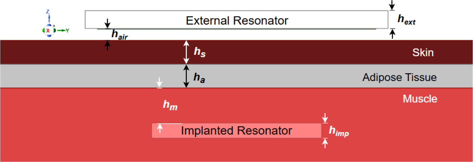
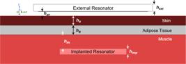
A 3-layer model comprising skin, adipose tissue, and muscle was used to model human tissues. This 3-layer model provided close results between simulation and measurement in previous works [19]- [21]. According to the IT’IS Foundation database [22], the relative permittivity (ϵr), conductivity (σ), and mass density (ρ) of skin, adipose tissue, and muscle at 403 MHz are listed in Table I. In the simulation, the implanted resonator (Rx) is inserted into the muscle layer, while the external resonator (Tx) is placed 1 mm above the skin layer Fig. 1.
C. External resonator design
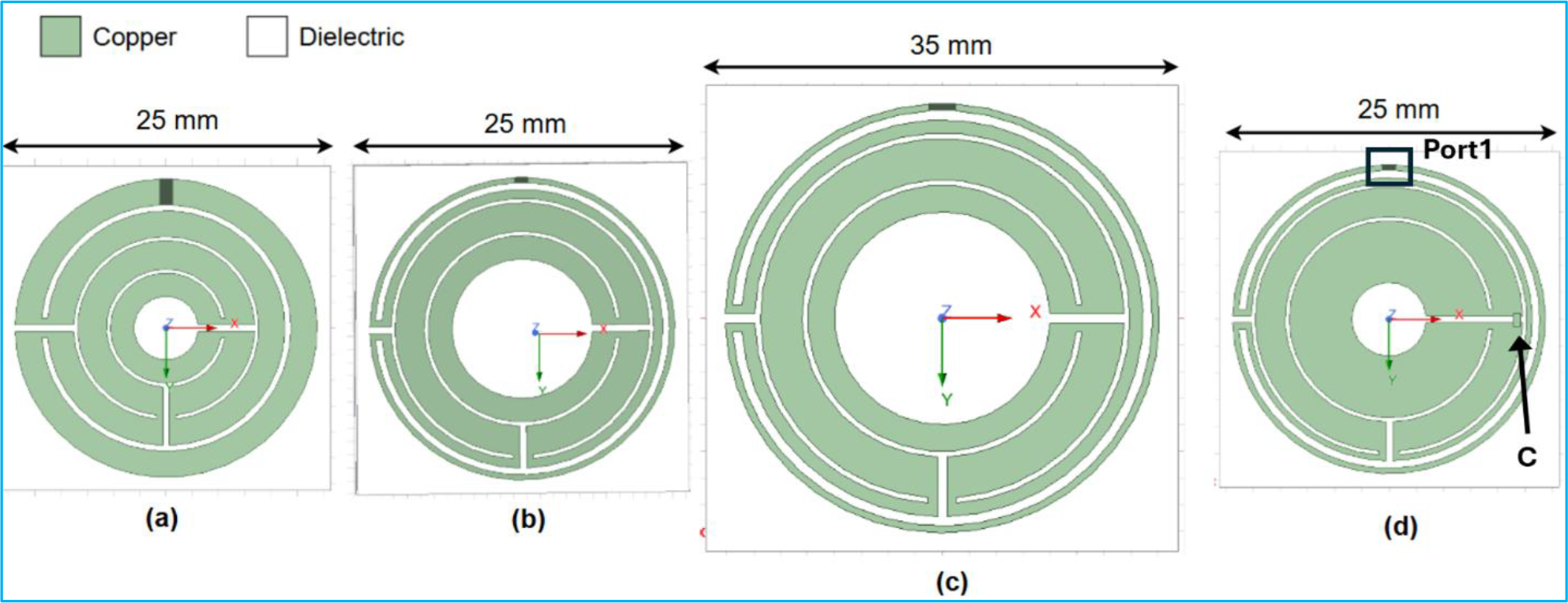
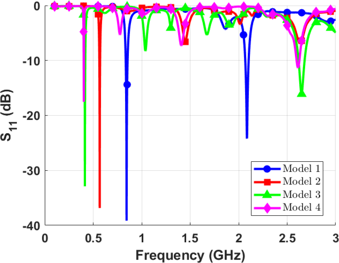
Four resonator models are proposed, each fed through Port 1, which is matched to an impedance of 50 Ohms Fig. 2. The substrate used is Rogers RO3006 (ϵr = 6.15) with a thickness hext of 1.52 mm. Model 1 is inspired by the Tx resonator presented in [20]. It consists of four loops, each with a width of 1mm Fig. 2(a). However, its lowest resonant frequency is located at 844 MHz. In Model 2, the width of each loop is optimized to reduce the resonant frequency Fig. 2(b). Despite this, the lowest resonant frequency is still too high for the MICS band, at 567 MHz. Models 3 and 4 explore two different strategies to reduce the resonant frequency. In Model 3, the size is increased to 35 mm x 35 mm, increasing the electrical length of the resonator and decreasing the frequency Fig. 2(c). This design resonance at 416 MHz. In Model 4, the size remains 25mm x 25mm as in Models 1 and 2, but a lumped capacitor of 6.2 pF is introduced Fig. 2(d). The added capacitance lowers the resonant frequency. The width of the inner loop (W4) is optimized to obtain a proper impedance matching. This approach successfully shifts the resonant frequency into the MICS band, achieving a resonance at 403 MHz, as shown in Fig. 3.
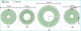
Evolution of the proposed Tx resonator: (a) Model 1. (b) Model 2. (c) Model 3. (d) Model 4 with Capacitor.

D. Implanted resonator design
The Rx resonator is implanted in the simulations in the muscle layer. It is an environment with high loss and frequency-dependent. The size of the Rx resonator directly influences its gain. As the resonator size decreases, the gain also decreases. This reduction in gain leads to a lower radiation efficiency, which is considered the main factor contributing to the reduction PTE [8]. The main challenge in designing the Rx is to minimize its size without significantly reducing PTE. In [20] and [21] the Rx dimensions are 25.5 mm x 25.5 mm x 1.52 mm (98.9 × 10⁻⁶ m3) and 17 mm x 17 mm x 1.52 mm (43.9 × 10⁻⁶ m3) respectively. The choice of a high dielectric substrate was made to reduce the Rx dimensions. Indeed, the guided wavelength (λg) is influenced mainly by the relative permittivity of the Rx substrate, when considered a non-magnetic material, as shown in (1):
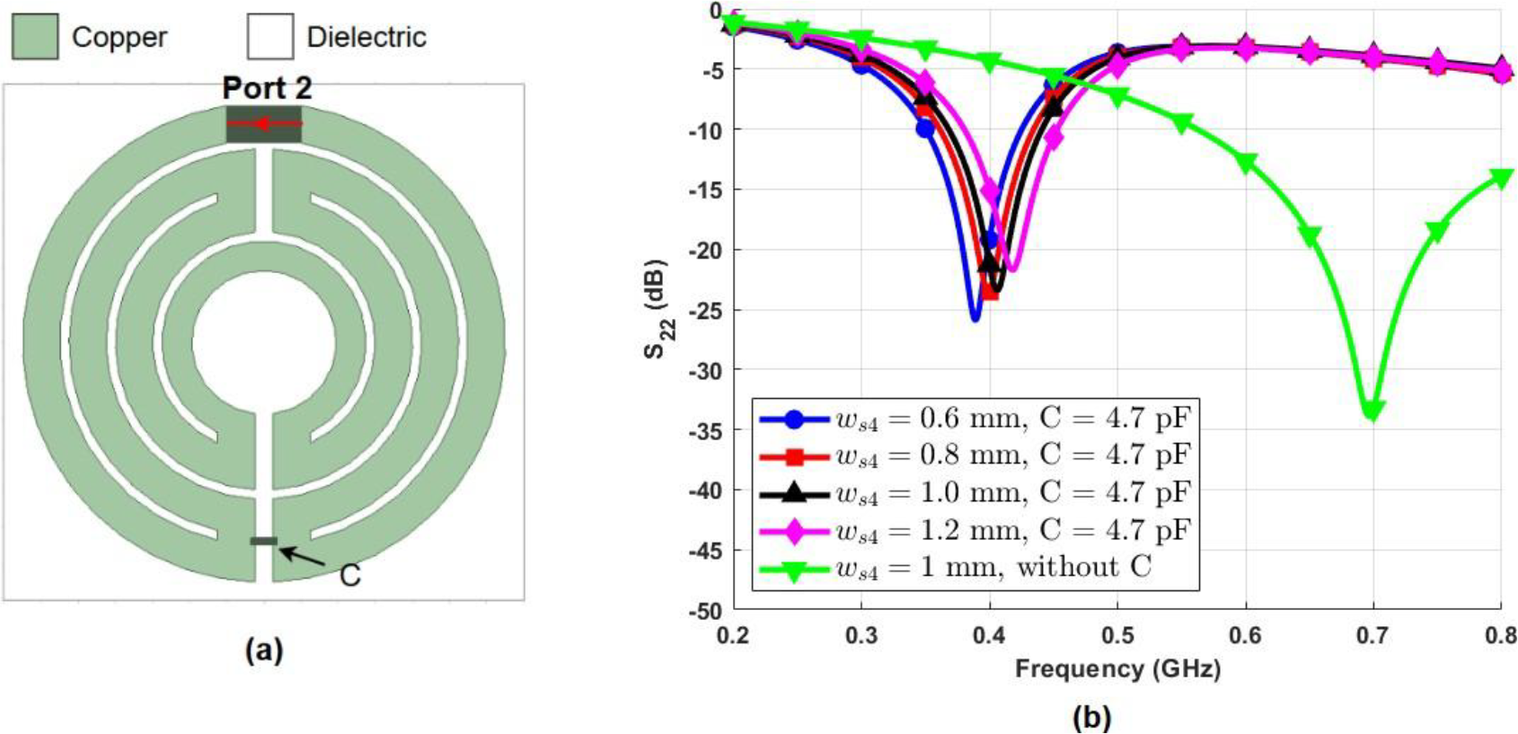
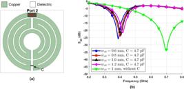
where λg is the guided wavelength, λo is the vacuum wavelength and ϵr is the relative permittivity of the Rx substrate. A decrease in the guided wavelength enables a reduction in the Rx size required for resonance at a specific frequency [8]. The substrate used is a Rogers RO3010 (ϵr = 10.2) with a thickness himp of 1.27 mm. The design of the proposed Rx is inspired from the Tx of [21]. To achieve a real reduction in the dimensions of the implanted element, maximum dimensions in the range of 14 mm were assigned. The simulated Rx has compact dimensions of 14 mm x 14 mm x 1.27 mm (24.9 × 10⁻⁶ m3). It comprises four loops. A lumped capacitor of 4.7 pF is used to reduce the resonance frequency, as shown in Fig. 4(a). Parametric analysis was performed to find the perfect value for the width of the inner loop ws4Fig. 4(b). At 403 MHz, the optimal S22 response is obtained for ws4 = 0.8 mm.
E. Simulated performance of the system
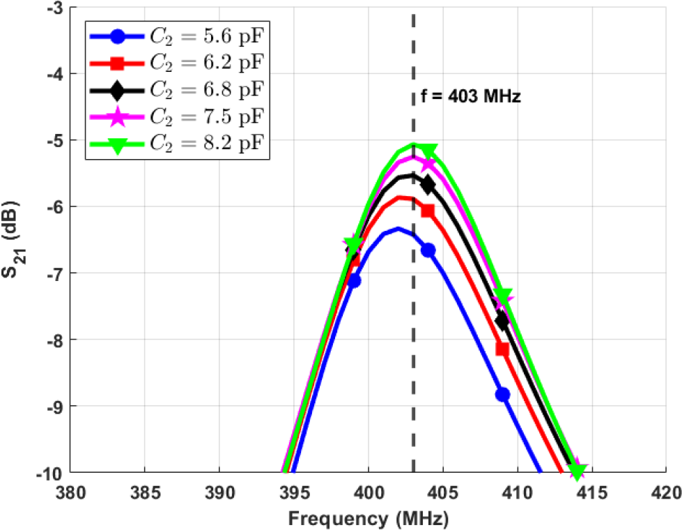
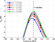
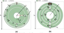
The performance of the WPT link is evaluated with the Rx embedded at a depth of hm within the muscle tissue, and the Tx positioned 1 mm above the skin surface. The values of the Rx capacitor (C2) is adjusted to achieve optimal impedance matching Fig. 5. The lumped capacitors are chosen as 6.2 pF (C1) and 8.2 pF (C2), respectively for the Tx and Rx resonators. The final geometry and parameters of both resonators are shown in Fig. 6, with the values listed in Table II.
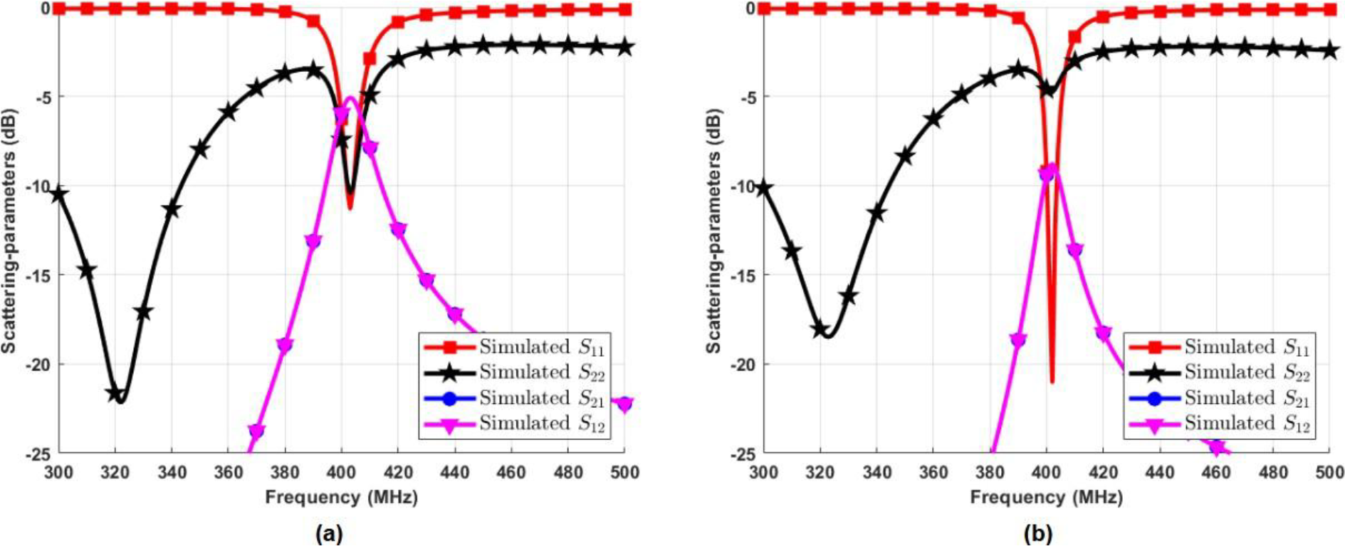
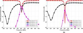
Based on the configuration described in Fig. 6(a) and Fig.6(b), a simulation was performed to obtain a frequency response of the WPT link, considering Port 1 and Port 2 matched to an impedance of 50 Ohms. A resonance at 403 MHz is present for both resonators. At a transfer distance of 8mm, the scattering parameters S11 and S22 are respectively equal to -10.42 dB and -11.28 dB. The transmission parameters S21 = S12 is equal to -5.07 dB (see Fig. 7(a)). When the transfer distance increases to 12 mm, S11 improves to -12.31 dB, whereas S22 degrades to -4.58 dB. The transmission parameters decrease to S21 = S12 = -8.99 dB (see Fig. 7(b)). This behavior of the scattering parameters may indicate that the inductive coupling between Tx and Rx is highly sensitive to the separation distance between the elements. Similarly, both the reflection coefficients at Ports 1 and 2 are modified with increasing distance.
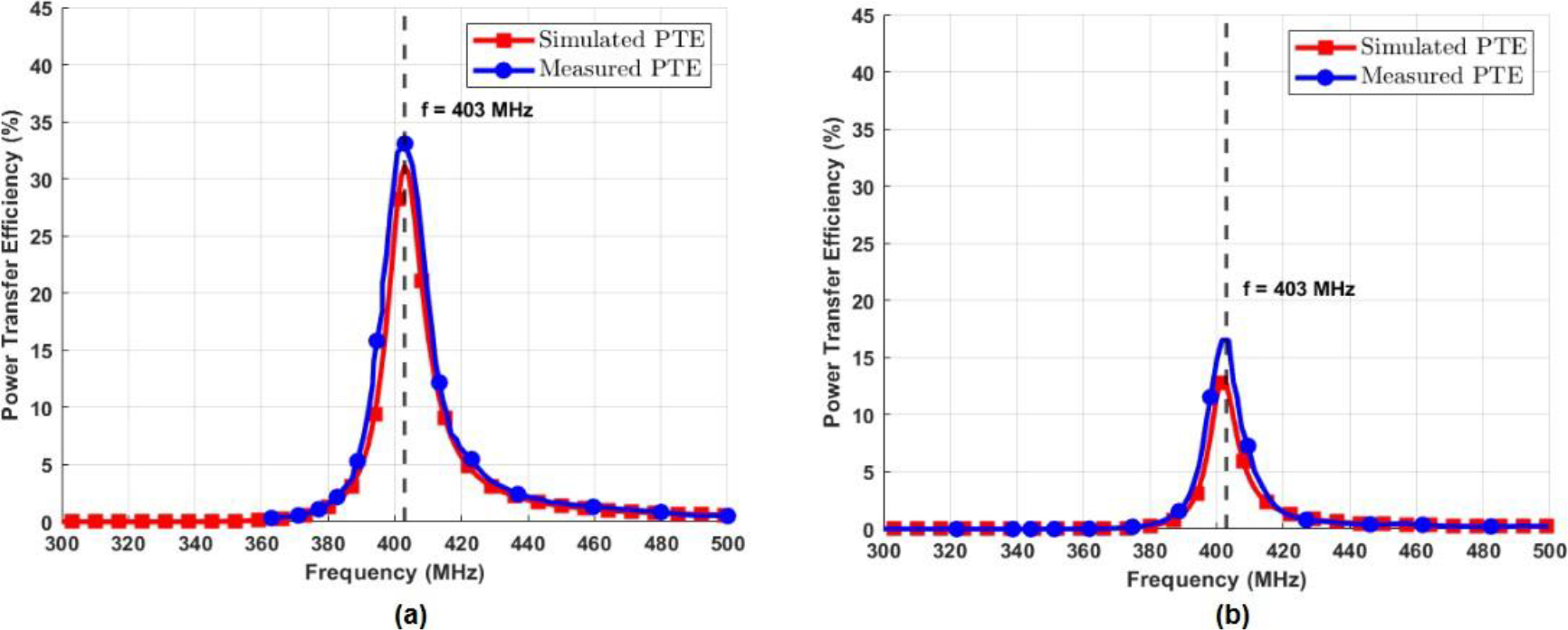
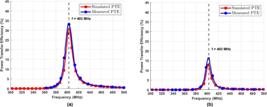
The PTE is a key parameter. It describes the amount of power transferred between the Tx and Rx resonator ports in terms of return loss. Equations (2) and (3) describe the PTE expression [19]-[21]. The is the RF efficiency, PRx and PTx are the received and transmitted power, respectively. Through the numerical results obtained via EM simulation, the PTE levels for the studied cases were analytically calculated using equations (2) and (3). The proposed WPT link achieves a peak PTE of 31.12% at 403 MHz when the transfer distance is 8 mm, maintaining efficiency above 28.9% across the MICS band (402 MHz - 405 MHz). At a greater distance of 12 mm, the PTE peaks at 12.62%, with values staying above 9.8% throughout the same frequency range.
III. SYSTEM PERFORMANCE STUDY
A. Distance sensitivity
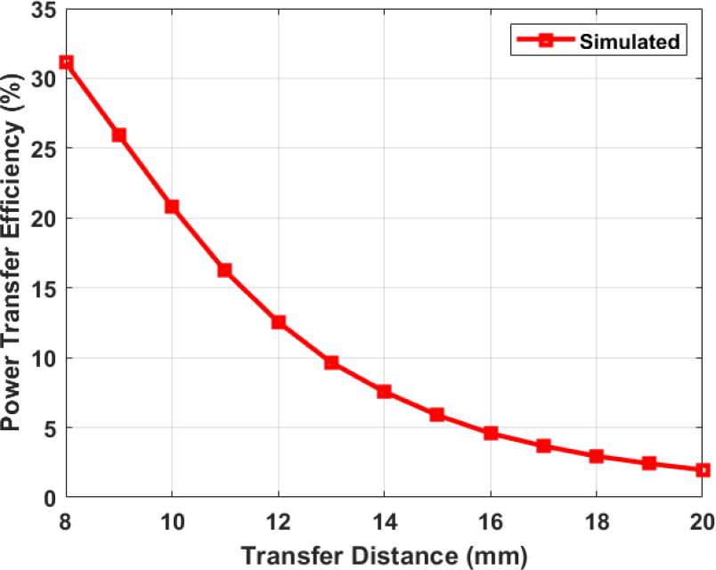
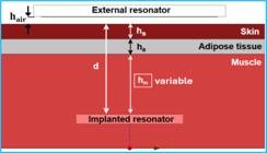
The implantation depth (d), defined in Fig. 8 as d = hs + ha + hm, affects the amount of power coupled between Tx and Rx [8]. It reduces the magnetic flux from Tx that perpendicularly crosses the Rx area [21]. At a transfer distance of 8 mm, the Rx-resonator is implanted at 7 mm in tissues because a 1 mm air gap () separates the skin from Tx-resonator. Simulations were conducted with an increase of the transfer distance between resonators. The depth adjustment was performed by increasing , thus representing an increase in implant depth within the muscle tissue. The Tx-resonator stays 1 mm above the skin; only the implanted depth (d) changes, with the other thickness parameters being kept constant. The influence of transfer distance on the PTE is shown in Fig. 9. A strong decrease is observed, with a PTE of 12.62% at 12mm and 1.96% at 20 mm.

B. Misalignment sensitivity
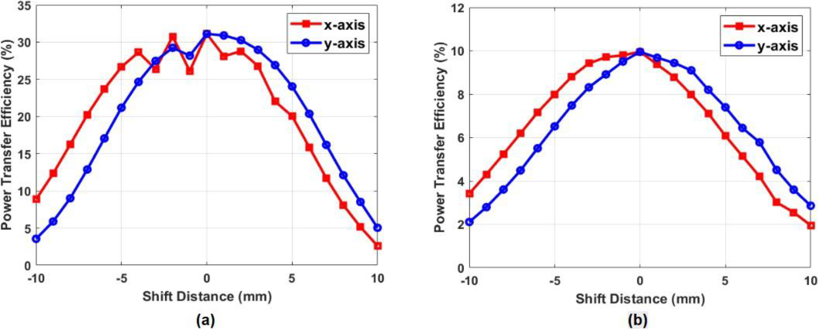
NRIC systems are highly sensitive to misalignment, a slight misalignment between resonators can lead to a significant reduction in the PTE [8]. The lateral displacement of the Tx-resonator was analysed along both the x-axis and y-axis. The simulation results for transfer distances of 8 mm and 12 mm are presented in Fig. 10(a) and Fig. 10(b). At 8 mm, the PTE decreases rapidly when the lateral misalignment exceeds ±3 mm, but remains above 20% up to ±5 mm. For a 12 mm distance, the PTE remains above 6% up to ±5 mm. These results prove that misalignment, on both axes, implies significant reductions in PTE. This fact is conclusive because, depending on the type of coupling (inductive), misalignment causes the leakage of magnetic field lines and consequently, reductions in magnetic flux. The result of this effect is a reduction in total PTE.
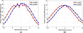
Simulated impact of lateral misalignment on PTE at transfer distances of (a) 8 mm and (b) 12 mm.
C. Specific Absorption Rate study
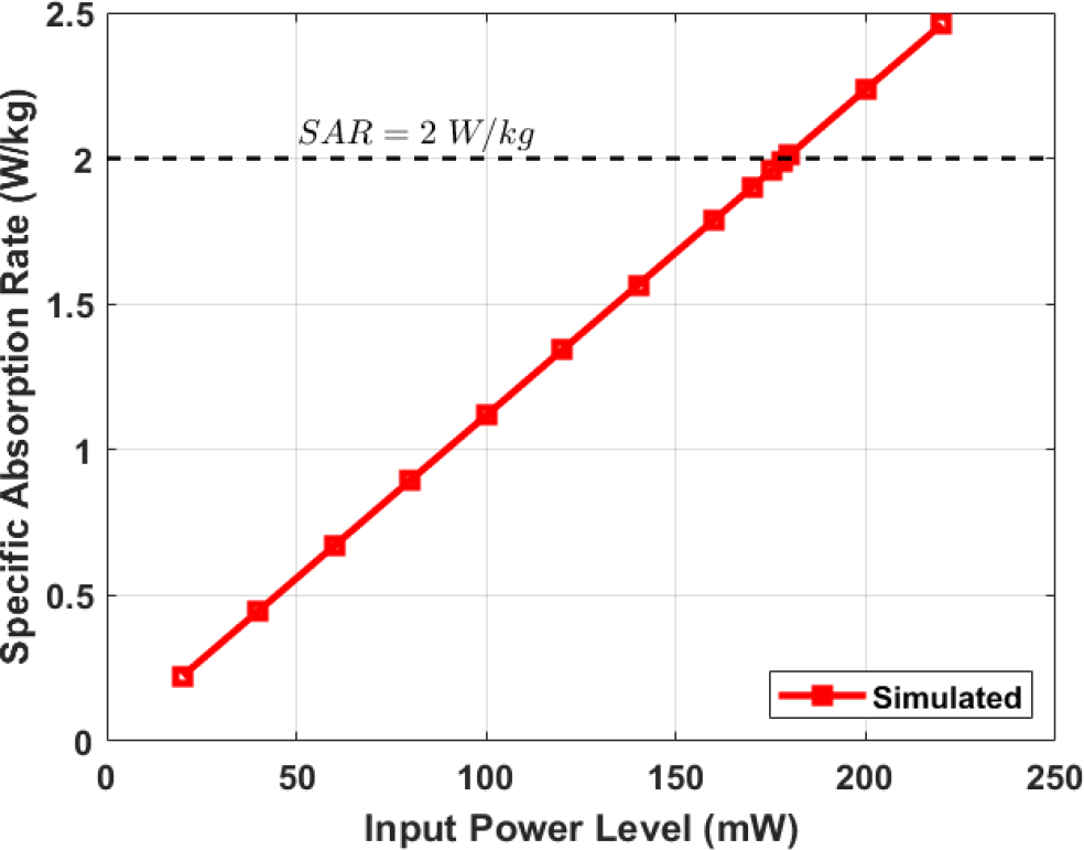
Specific Absorption Rate (SAR) is a measure of the rate at which EM energy is absorbed by the human’s biological tissues (per unit mass) when exposed to EM waves [11], [23]. According to the IEEE C95.1-2019 standards [24], the 10 g averaged SAR should be less than 2 W/kg for head and torso exposure. Numerical simulations were performed using Ansys HFSS software to obtain SAR values at 403 MHz. A human torso was used together with the WPT system. The study of the SAR as a function of the input power was carried out, as described in Fig. 11. The black horizontal dotted line represents the 10 g averaged SAR limitation of 2 W/kg.

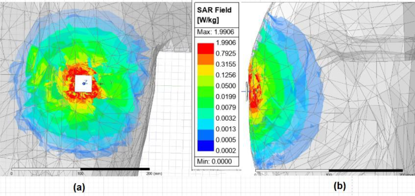
The red line shows the calculated SAR values for this WPT link. A linear increase of SAR is observed. For Ptx = 20 mW, a maximum SAR in the tissues of the Tx-Rx link region of 0.224 W/kg was obtained. To comply with the IEEE SAR regulations, the maximum input power at the Tx-resonator should be less than 178 mW at 403 MHz. With the maximum RF-RF efficiency (due exclusively to the wireless coupling between Tx and Rx) of 31.12% at an 8 mm transfer distance, the Rx can receive a maximum power of 55.39 mW, complying with the safety limits. The distribution of SAR in human tissues at 403 MHz and PT x = 178 mW is shown in Fig. 12(a) and Fig 12(b).
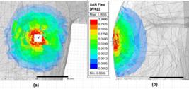
Distribution of SAR in human tissues at 403 MHz for PTx = 178mW . (a) Front view (b) Side view.
IV. RESULTS AND DISCUSSION
A. Measurement setup
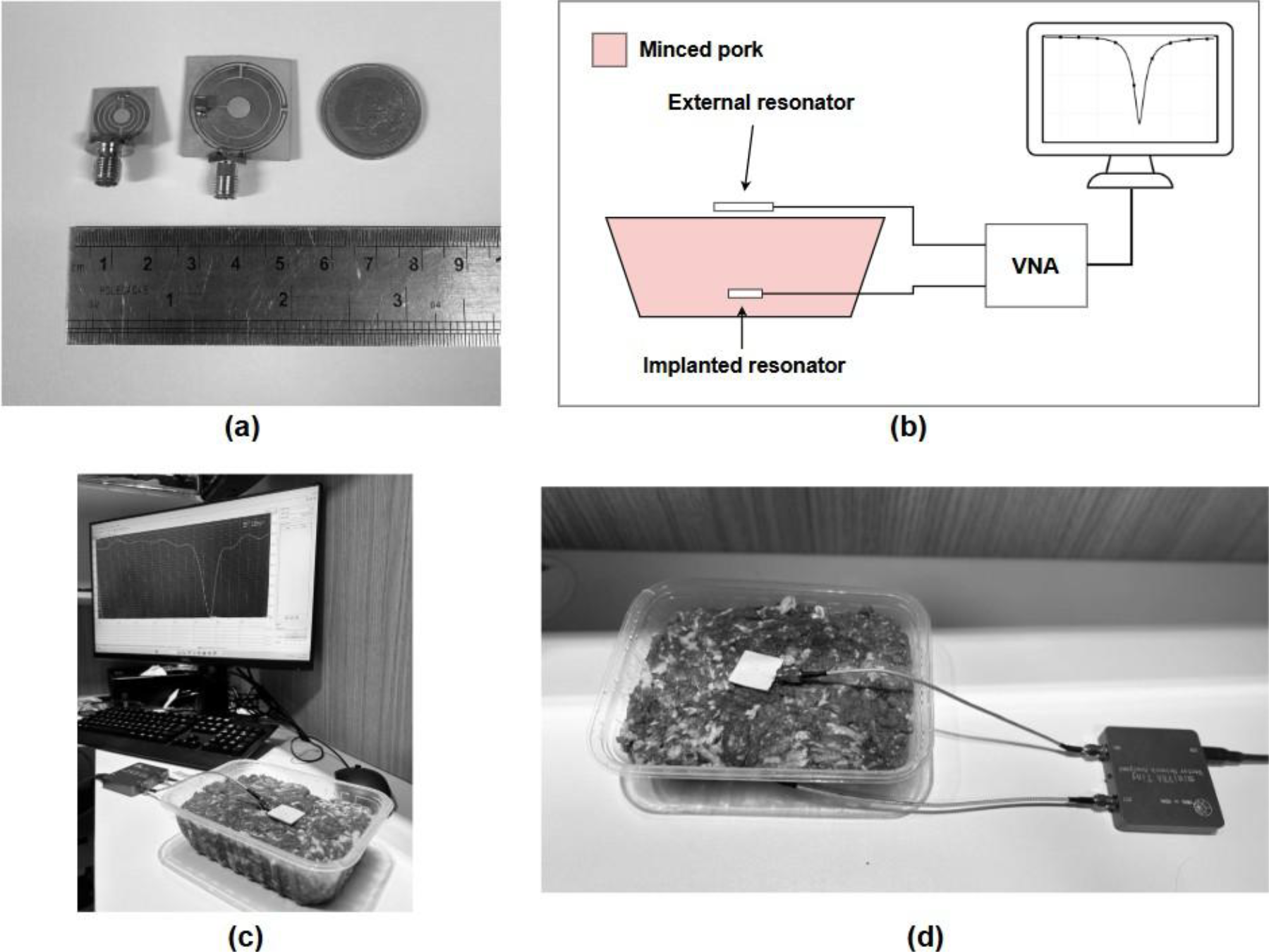
The proposed Tx and Rx were fabricated on Rogers RO3006 and RO3010 substrates, respectively Fig. 13(a). The thickness of the copper is 35 µm. The prototypes were manufactured through a controlled corrosion process using ferric chloride with the aid of adhesive templates in the shape of the inductive elements. The total dimensions of resonators are 95 × 10-6 m3 for Tx and 24.9 × 10⁻⁶ m3 for Rx. Surface Mount Device (SMD) capacitors of 6.2 pF (C1) and 8.2 pF (C2) are soldered. Bench measurements were performed using a Vector Network Analyzer (VNA), calibrated for a 50.0 Ω input impedance at both ports. SMA connectors are soldered and connected to the two VNA ports Fig. 13(b). To simulate human tissues, the Rx resonator is inserted into fresh minced pork. Figs. 13(c) and Fig. 13(d) show the assembly of the measurement setup considering the positioning of the Tx and Rx elements next to the animal protein samples. Within the frequency range of interest, minced pork has been shown to possess electromagnetic properties that closely resemble those of a layered structure that comprises skin, adipose tissue, and muscle tissue [19]-[21], [25]. The 1mm separation was implemented through the use of thin film paper with a permittivity close to 1 and negligible losses.
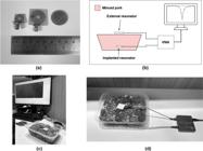
(a) Fabricated resonators. (b) Schematic of the experimental setup. (c)-(d) Experimental setup.
B. Experimental results and discussion
Measurements were conducted for two transfer distances: 8 mm and 12 mm. A comparison between the measured and simulated S-parameters is presented in Fig. 14. At 8 mm, simulation and measurement are very close in the 402 MHz - 405 MHz band. At 403 MHz, the measured S11, S22, S21 and S12 are -12.09 dB, -10.80 dB, -4.81 dB and -4.81 dB, respectively Fig. 14(a) and Fig. 14(b). At 12 mm, a marked difference is observed between the measured and simulated reflection coefficients S22, as shown in Fig. 14(c). Specifically, the simulated value is S22 = -4.58 dB, whereas the measured value is S22 = -12.28 dB. This indicates a deviation of approximately 7.7 dB, highlighting a significant mismatch between the simulation and the experimental results for S22. However, this deviation has no significant impact on the transmission coefficients, which are critical parameters for determining the PTE Fig. 14(d). Fig. 15(a) and Fig. 15(b) presents the comparison between simulated and measured PTE. Compared to simulation results, a slight improvement at 403 MHz is achieved in measurement, with values reaching 33.11% at 8 mm and 16.54% at 12 mm. It can be reported that the water concentration in the tissues can cause momentary variations in the electric permissive conditions of the animal protein used, resulting in possible significant improvements or reductions in system performance.
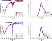
Simulated and measured scattering parameters. (a) Reflection coefficients at 8 mm. (b) Transmission coefficients at 8 mm. (c) Reflection coefficients at 12 mm. (d) Transmission coefficients at 12 mm.
A comparison with other works is shown in Table III. At a separation distance of 12 mm, the proposed system achieves a higher PTE compared to previous works employing split-ring loops geometries, despite the reduced dimension of the Tx and Rx resonators. The simulated PTE at 12 mm reported in [20] is approximately 12.5% at 12 mm, while in [21] it is close to 10%. However, at a transfer distance 8mm, the PTE is significantly lower compared to the results presented in [20] and [21]. The dimensions of the Rx are reduced through the inclusion a capacitor to shift the resonant frequency and the use of a high-dielectric-constant substrate. As a result, the Rx surface area was reduced by approximately 331% compared to [20], 47% compared to [21], and 22% compared to [19]. EM simulations demonstrate reduced sensitivity to misalignment compared to the system reported in [21]. At an 8 mm transfer distance
the PTE remains above 20% for lateral misalignment up to ±5 mm. The resulting compact size is sufficient to allow integration within implantable medical devices such as cardiac pacemakers or neurostimulators. The maximum received power, limited by SAR regulations, reaches 29.44 mW at a distance of 12 mm. This value exceeds the results reported in [20] and [21] at the same distance, and even surpassing the maximum received power at 5 mm reported in [19]. This level of maximum received power is sufficient to power implantable devices such as pacemakers, cochlear implants, and certain neurostimulators [27].
V. CONCLUSION
This article presented a 403 MHz non-radiative WPT system based on inductive coupling, designed for applications in IMDs. This system operates in the MICS band, which is internationally allocated for medical implant communication. By integrating multiple split-ring loops with a high-dielectric substrate and a capacitor, Rx achieves strong performance in a compact size of only 14 mm x 14 mm x 1.27 mm (24.9 × 10⁻⁶ m3). This design significantly reduces the size compared to previous work, with a reduction in surface area exceeding 20%. The measured PTE reaches up to 16.54% at a transfer distance of 12 mm through living tissues. EM simulations confirm compliance with regulatory SAR limits, remaining below 2 W/kg for an input power of up to 178.0 mW at 403 MHz. A comparative analysis with existing literature demonstrated a significant reduction in Tx and Rx dimensions compared to several previously proposed models, improved PTE at a 12 mm distance, and an increase in maximum received power. Therefore, the proposed WPT system represents a promising alternative to power IMDs. However, the system remains sensitive to misalignment, and the PTE could be further improved at longer transfer distances to enable deeper implantation of medical devices.
ACKNOWLEDGMENTS
This study was financed in part by the Coordenação de Aperfeiçoamento de Pessoal de Nível Superior - Brasil (CAPES) - Finance Code 001, Federal University of Rio Grande do Norte (UFRN), LabModel- UFRN (Laboratory of Modeling, Circuits and Signal Analysis) and the National Council for Scientific and Technological Development (CNPq).
DATA AVAILABILITY
The data underlying this study are available in the published article. Raw data that support the findings of this study are available from the corresponding authors, upon reasonable request.
REFERENCES
-
[1] A. M. Jawad, R. Nordin, S. Gharghan, H. M. Jawad, and M. Ismail, “Opportunities and challenges for near-field wireless power transfer: A review,” Energies, vol. 10, no. 7, pp. 1022-1049, 2017, DOI: https://doi.org/10.3390/en10071022
» https://doi.org/10.3390/en10071022 -
[2] M. Ramzan, A. Khaleghi, X. Fang, Q. Wang, N. Neumann, and D. Plettemeier, “An ultra-miniaturized high efficiency implanted spiral antenna for leadless cardiac pacemakers,” IEEE Transactions on Biomedical Circuits and Systems, vol. 17, no 3, pp. 621-632, 2023, DOI: 10.1109/TBCAS.2023.3285451.
» https://doi.org/10.1109/TBCAS.2023.3285451. -
[3] R. Li, Y. Zhang, X. Chu, L. Gan, J. Li, B. Li, and H. Du, “Design and numerical study of induction-heating graphitization furnace based on graphene coils,” Applied Sciences, vol. 14, no. 6, pp. 2528-2544, 2024, DOI: https://doi.org/10.3390/app14062528
» https://doi.org/10.3390/app14062528 -
[4] L. Dodds, N. Naeem, A. Eid, and F. Adib, “Software-controlled polarization for longer-range RFID reading and localization,” 2023 IEEE International Conference on RFID, p. 90-95, 2023, DOI: 10.1109/RFID58307.2023.10178674.
» https://doi.org/10.1109/RFID58307.2023.10178674. -
[5] C. L. Kok, X. Fu, Y. Y. Koh, and T. H. Teo, “A novel portable solar powered wireless charging device,” Electronics, vol. 13, no. 2, pp. 403-418, 2024, DOI: https://doi.org/10.3390/electronics13020403
» https://doi.org/10.3390/electronics13020403 -
[6] K. Agarwal, R. Jegadeesan, Y. X. Guo, and N. V. Thakor, “Wireless power transfer strategies for implantable bioelectronics,” IEEE Reviews in Biomedical Engineering, vol. 10, pp. 136-161, 2017, DOI: 10.1109/RBME.2017.2683520.
» https://doi.org/10.1109/RBME.2017.2683520. -
[7] H. Dinis, I. Colmiais, and P. M. Mendes, “Extending the limits of wireless power transfer to miniaturized implantable electronic devices,” Micromachines, vol. 8, no. 12, pp. 359-373, 2017, DOI: https://doi.org/10.3390/mi8120359
» https://doi.org/10.3390/mi8120359 -
[8] A. Essa, E. Almajali, S. Mahmoud, R. E. Amaya, S. S. Alja’Afreh, and M. Ikram, “Wireless power transfer for implantable medical devices: Impact of implantable antennas on energy harvesting,” IEEE Open Journal of Antennas and Propagation, vol. 5, no. 3, pp. 739-758, 2024, DOI: 10.1109/OJAP.2024.3392160.
» https://doi.org/10.1109/OJAP.2024.3392160. -
[9] A. Basir and H. Yoo, “Efficient wireless power transfer system with a miniaturized quad-band implantable antenna for deep-body multitasking implants,” IEEE Transactions on Microwave Theory and Techniques, vol. 68, pp. 1943-1953, 2020, DOI: 10.1109/RBME.2017.2683520.
» https://doi.org/10.1109/RBME.2017.2683520. -
[10] L. Tung and C. Seo, “A miniaturized implantable antenna for wireless power transfer and communication in biomedical applications,” Journal of Electromagnetic Engineering and Science, vol. 22, no. 4, pp. 440-446, 2022, DOI: 10.26866/jees.2022.4.r.107.
» https://doi.org/10.26866/jees.2022.4.r.107. -
[11] J. Zhang, R. Das, D. Hoare, H. Wang, A. Ofiare, N. Mirzai, J. Mercer and H Heidari, “A compact dual-band implantable antenna for wireless biotelemetry in arteriovenous grafts,” IEEE Transactions on Antennas and Propagation, vol. 71, no. 6, pp. 4759-4771, 2023, DOI: 10.1109/TAP.2023.3266786.
» https://doi.org/10.1109/TAP.2023.3266786. -
[12] J. G. D. Junior, A. G. D’Assuncao, and V. P. S. Neto, “A new efficient dual-band circularly polarized implantable patch antenna for wireless power transfer,” IEEE Antennas and Wireless Propagation Letters, vol. 24, no. 2, pp. 294-298, 2024, DOI: 10.1109/LAWP.2024.3488575.
» https://doi.org/10.1109/LAWP.2024.3488575. -
[13] D. Sharma, S. Kumar, N. Singh, B. K. Kanaujia, S. P. Singh, and A. Lay-Ekuakille, “Far-field wireless power transmission and measurement for a leadless transcatheter pacing system,” IEEE Transactions on Instrumentation and Measurement, vol. 72, pp. 1-12, 2023, DOI: 10.1109/TIM.2023.3302377.
» https://doi.org/10.1109/TIM.2023.3302377. -
[14] M. Wang and al, “Broadband implantable antenna for wireless power transfer in cardiac pacemaker applications,” IEEE Journal of Electromagnetics, vol. 5, no. 1, pp. 2-8, 2021, DOI: 10.1109/JERM.2020.2999205.
» https://doi.org/10.1109/JERM.2020.2999205. -
[15] A. Iqbal, M. Al-Hasan, I. B. Mabrouk, A. Basir, M. Nedil, and H. Yoo, “Biotelemetry and wireless powering of biomedical implants using a rectifier integrated self-diplexing implantable antenna,” IEEE Transactions on Microwave Theory and Techniques, vol. 69, no. 7, pp. 3438-3451, 2021, DOI: 10.1109/TMTT.2021.3065560.
» https://doi.org/10.1109/TMTT.2021.3065560. -
[16] T. Shaw, B. Mandal, D. Mitra, P. K. B. Rangaiah, M. D. Perez, and R. Augustine, “Wireless power transfer system design using zero-index metamaterial for implantable medical devices,” 17th European Conference on Antennas and Propagation (EuCAP), pp. 1-5, 2023, DOI: 10.23919/EuCAP57121.2023.10133695.
» https://doi.org/10.23919/EuCAP57121.2023.10133695. -
[17] M. Haerinia and R. Shadid, “Wireless power transfer approaches for medical implants: A review,” Signals, vol. 31, no. 2, pp. 209-229, 2020, DOI: https://doi.org/10.3390/signals1020012
» https://doi.org/10.3390/signals1020012 -
[18] S. Miziev, W. Pawlak, and N. Howard, “Comparative analysis of energy transfer mechanisms for neural implants,” Frontiers in Neuroscience, vol. 17, pp. 1-20, 2023, DOI: https://doi.org/10.3389/fnins.2023.1320441
» https://doi.org/10.3389/fnins.2023.1320441 -
[19] G. Monti, M. D. Paolis, L. Corchia, M. Mongiardo, and L. Tarricone, “Inductive link for power and data transfer to a medical implant,” Wireless Power Transfer, vol. 4, no. 2, pp. 98-112, 2017, DOI: 10.1017/wpt.2017.6.
» https://doi.org/10.1017/wpt.2017.6. -
[20] J. Wang, E. G. Lim, M. P. Leach, Z. Wang, R. Pei, Z. Jiang and Y. Huang, “A 403 MHz wireless power transfer system with tuned split-ring loops for implantable medical devices,” IEEE Transactions on Microwave Theory and Techniques, vol. 70, no. 2, pp. 1355-1366, 2022, DOI: 10.1109/TAP.2021.3111520.
» https://doi.org/10.1109/TAP.2021.3111520. -
[21] J. G. D. Júnior, A. G. D’Assunção, F. A. Brito-Filho, and V. P. da Silva Neto, “An efficient wireless power transfer system planar turn based for implantable medical devices applications,” Measurement, vol. 235, pp. 1-11, 2024, DOI: 10.1016/j.measurement.2024.115014.
» https://doi.org/10.1016/j.measurement.2024.115014. -
[22] IT’IS Foundation, Database of Tissue Properties. [Online]. Available: https://itis.swiss/virtual-population/tissueproperties/overview/ Accessed: August 15, 2025.
» https://itis.swiss/virtual-population/tissueproperties/overview/ -
[23] I. V. Soares and U. C. Resende, “Radially periodic metasurface lenses for magnetic field collimation in resonant wireless power transfer applications,” Journal of Microwaves, Optoelectronics and Electromagnetic Applications, vol. 21, no. 1, pp. 48- 60, 2022, DOI: https://doi.org/10.1590/2179-10742022v21i1253604
» https://doi.org/10.1590/2179-10742022v21i1253604 -
[24] INSTITUTE OF ELECTRICAL AND ELECTRONICS ENGINEERS (IEEE), "IEEE Standard for Safety Levels with Respect to Human Exposure to Electric, Magnetic, and Electromagnetic Fields, 0 Hz to 300 GHz," IEEE Std C95.1-2019, pp. 1-312, 2019, DOI: 10.1109/IEEESTD.2019.8859679.
» https://doi.org/10.1109/IEEESTD.2019.8859679. -
[25] G. Monti, P. Arcuti, and L. Tarricone, “Resonant inductive link for remote powering of pacemakers,” IEEE Transactions on Microwave Theory and Techniques, vol. 63, no. 11, pp. 3814-3822, 2015, DOI: 10.1109/TMTT.2015.2481387.
» https://doi.org/10.1109/TMTT.2015.2481387. -
[26] M. M. M. Tamura, T. Segawa, “Capacitive coupler for wireless power transfer to intravascular implant devices,” IEEE Microwave and Wireless Components Letters, vol. 32, no. 6, pp. 672-675, 2022, DOI: 10.1109/LMWC.2022.3160688.
» https://doi.org/10.1109/LMWC.2022.3160688. -
[27] R. Guida and T. Melodia, “Powering smart wireless implantable medical devices: Toward an internet of self-powered intra-body things,” Ad Hoc Networks, vol. 169, pp.1-35, 2025, DOI: https://doi.org/10.1016/j.adhoc.2024.103748
» https://doi.org/10.1016/j.adhoc.2024.103748
-
Editor:
Carlos E. Capovilla
-
Associate Editor:
Karlo Costa