Analytical FIR Optical Filter Based on Time-Delayed Photonic Neural Networks for 40 Gbps NRZ Dispersion Compensation
Abstract
This paper presents an analytical method for designing FIR filters based on the hardware of time-delayed photonic neural networks for chromatic dispersion compensation in long-reach passive optical networks. The model employs a Fourier-based synthesis of the compensation function, allowing for the closed-form determination of phase and amplitude weights for each optical path. Different implementation strategies are considered, including solutions with phase-only control and others with additional amplitude control using tunable attenuators. Simulations over a 100 km standard single-mode fiber link demonstrate effective dispersion compensation for NRZ-OOK signals. In particular, the symmetric FIR-based design with 23 optical paths and 25 ps delay spacing achieved BER < 10-3 at data rates up to 40 Gbps under amplified spontaneous emission noise. These results confirm the analytical approach's potential to provide scalable, power-efficient, and high-speed solutions for future long-reach optical access networks.
Index Terms
Chromatic dispersion compensation; FIR optical filters; photonic neural networks; long-reach PONs
I. INTRODUCTION
The increasing demand for high-capacity and extended-reach optical access networks has driven the evolution of long-reach passive optical network (LR-PON) architectures. These systems aim to extend transmission distances from conventional spans of approximately 20 km to values approaching or exceeding 100 km, as discussed in [1]. This approach enables the consolidation of central offices and reduces infrastructure costs, making LR-PON a promising solution for future broadband access networks. However, increasing transmission distance significantly exacerbates chromatic dispersion, which becomes a major limiting factor, particularly in systems based on intensity modulation and direct detection (IMDD).
To mitigate chromatic dispersion in optical fiber links, several techniques have been proposed. Dispersion-compensating fibers (DCF) provide effective compensation but suffer from high attenuation and large physical length, making them unsuitable for photonic integration [2], [3]. Fiber Bragg gratings (FBG) offer an alternative solution; however, their implementation requires direct inscription in optical fibers, limiting their compatibility with integrated photonic platforms [3]. Electronic dispersion compensation (EDC) is widely used and highly flexible, but it introduces additional latency and power consumption due to digital signal processing, which conflicts with the requirements of low-power optical access systems [3].
With advances in integrated photonics, optical-domain solutions based on photonic integrated circuits have gained significant attention. Among these, finite impulse response (FIR) optical filters implemented using interferometric structures, such as Mach-Zehnder interferometers (MZIs), have emerged as a promising approach for dispersion compensation [4]. Several implementations have been reported in the literature. Rahim et al. [5] proposed a tunable residual dispersion compensator based on generalized MZIs, in which thermo-optic phase shifters are used to control the group-delay response. Liu et al. [6] demonstrated an adaptive FIR filter implemented in a photonic integrated circuit, in which filter coefficients are continuously updated through adaptive algorithms. Huang et al. [7] introduced a hybrid optical-electrical equalization scheme combining optical delay lines with digital signal processing. Lang et al. [8] proposed an on-chip FIR-based dispersion compensator using asymmetric MZIs and phase tuning based on zero placement. More recently, Hui et al. [9] explored dispersion compensation using cascaded microring resonators, relying on group delay engineering in resonant structures.
Although these approaches demonstrate feasibility, they typically rely on thermal tuning, adaptive optimization, or hybrid processing, meaning the mapping between the desired compensation function and the physical hardware parameters is determined through iterative or numerical procedures, thereby limiting scalability and increasing system complexity.
In particular, there is a lack of methods capable of directly mapping the analytical expression of the chromatic dispersion compensation function into the parameters of a photonic FIR filter, without relying on optimization algorithms or electronic signal processing. This limitation becomes especially relevant in architectures aiming at low-complexity and energy-efficient implementations for IMDD systems.
In this context, photonic neural network (PNN) hardware, particularly in the form of time-delayed photonic perceptrons as proposed by Mancinelli et al. [10], provides a suitable physical platform for implementing multi-tap optical filters. Although originally introduced for neuromorphic applications, this architecture is interpreted in this work as a linear system equivalent to an FIR filter, in which delayed optical replicas are combined via interferometric superposition with programmable phase shifts.
Building upon this interpretation, this work proposes a closed-form analytical framework for designing optical FIR filters using a photonic perceptron architecture as the physical implementation platform. The method employs a Fourier-series-based synthesis of the chromatic dispersion compensation function, enabling the direct computation of phase and amplitude coefficients associated with each optical path. In this way, the perceptron hardware is systematically configured to realize a target FIR response without the need for iterative optimization or adaptive algorithms.
To the best of our knowledge, this is one of the first works to provide a closed-form analytical mapping between the chromatic dispersion compensation function and the physical parameters of a photonic FIR filter.
The proposed method is evaluated through system-level simulations using the Ansys Lumerical INTERCONNECT® environment, considering NRZ-OOK transmission over a 100 km standard single-mode fiber link. Different implementation scenarios are analyzed, including phase-only and amplitude-controlled configurations, as well as a time-shifted symmetric FIR formulation.
II. THEORETICAL DEVELOPMENT
A mathematical formulation based on the Fourier series is employed to derive an analytical solution for chromatic dispersion compensation in the form of an FIR filter. The objective is to directly determine the filter coefficients and map them onto the parameters of a photonic hardware platform, specifically the time-delayed photonic perceptron architecture. This approach supports the design of an optical FIR-type filter that functions as a chromatic dispersion equalizer [11]. Meltenisov et al. [12] proposed an analytical representation of the phase constant of the optical signal, β(ω), which characterizes light propagation in optical fibers, as also described by Agrawal [13]. This representation is given by:
where β0 is the propagation constant at the reference angular frequency ω0, β1is associated with the group velocity and β2 represents the second-order dispersion.
In the adopted method, only the second-order dispersion term, from Eq. (1), is considered relevant for chromatic dispersion compensation. Accordingly, the frequency-domain transfer function of a single-mode optical fiber can be approximated as:
where z is the fiber length in meters, and ω0 is the central angular frequency of the optical signal. This approximation is valid within a finite spectral interval between ω1 and ω2, which also defines the period for the corresponding Fourier series expansion. Since dispersion effects accumulate predominantly within this range, the approximation neglects contributions from out-of-band components.
To counteract the dispersive phase shift introduced by the fiber, the chromatic dispersion compensator (CDC) function is defined as the complex conjugate of the transfer function in (2), that is,
The function G(ω) can be approximated by a Fourier series over the interval , enabling the synthesis of a finite impulse response (FIR) filter for chromatic dispersion compensation.
A. Theoretical Modeling of the Hardware of the Passive Optical Perceptron
To enable physical implementation of the analytically derived FIR filter, the time-delayed photonic perceptron architecture is adopted as the underlying hardware platform. In this context, the perceptron is not treated as a neural network model, but rather as a feedforward optical structure capable of realizing multi-tap FIR filtering through delayed and weighted signal replicas.
The optical neuron, also referred to as a photonic perceptron, was originally proposed by Mancinelli et al. [10]. Here, the term photonic perceptron refers strictly to its hardware implementation, which is employed as a linear FIR filter without any learning or nonlinear activation mechanism. Its operation relies on the coherent recombination of multiple temporally delayed replicas of the input optical signal, each modified by a programmable phase shift. In the generalized configuration, illustrated in Fig. 1, the perceptron comprises N optical paths with relative delays of 0, ∆t, 2∆t, ..., (N-1)∆t. These delays are implemented using optical spirals that also introduce propagation loss. The attenuation in each arm can be approximated by
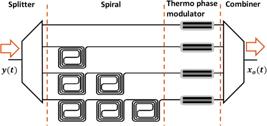
where ∆t is given in picoseconds and k ∈ {1, 2, ..., N} is the index of the k-th optical path. This formulation is consistent with the attenuation profile reported in [10].
The photonic architecture proposed by Mancinelli et al. [10] serves as the basis of the compensation scheme adopted in this work. In this model, the input optical signal xi(t) propagates through a dispersive single-mode fiber, whose impulse response is denoted by h(t), producing the output signal y(t). Subsequently, a compensator with impulse response g(t) is applied to generate the final output signal xo(t), such that the cascade
To express the effect of chromatic dispersion in the frequency domain, we define the modulation frequency as , where ω0 is the carrier frequency. Then, the frequency response of the fiber becomes:
where β2 is the group velocity dispersion (GVD) parameter and z is the fiber length.
The optical perceptron hardware is modeled as a feedforward structure whose operation is described by Eq. (6). In this architecture, delayed and weighted replicas of the received signal y(t) are combined: each optical path introduces a delay of (k 1)∆t, an amplitude scaling factor , and a phase shift φk, implemented through integrated delay lines, variable attenuators, and thermal phase shifters, respectively. This configuration is formally equivalent to an optical FIR filter and can therefore operate as a dispersion-compensating device.
Applying the Fourier transform to Eq. (6) and using Eq. (5), we obtain the total system response:
From the Fourier-domain representation in (7), the overall system transfer function can be factorized as:
where the compensation function implemented by the photonic perceptron hardware is expressed as
The design objective associated with the perceptron hardware is to configure the filter parameters so that the compensation function cancels the dispersion imposed by the fiber, making the product in (8) approximate unity within the spectral band of interest. In practice, this involves determining the phase shifts φk which define the contribution of each delayed path. This formulation establishes the link between the perceptron architecture and the FIR filter model, providing the foundation for the more general Fourier-based solutions developed in the following subsections.
B. Mathematical Model of the Non-Causal FIR Filter
In Meltenisov [11], a non-causal optical filter based on Fourier series coefficients is developed, operating over a specific sub-band, representing an approximation of the chromatic dispersion compensation function. In this work, this compensating function is expressed in terms of the modulation frequency and is described by in Eq. (3). This function, when approximated by a Fourier series, results in the function , which is defined as:
L,Δt: Half the width of the frequency sub-band used to define the Fourier period of , and the corresponding time delay introduced by the FIR filter. These parameters are given by
cn: The complex Fourier coefficient associated with the exponential basis of the Fourier series, defined as
Given that the modulation frequency is centered at , the integration limits are defined as and . Using Fresnel integrals, the closed-form solution of Eq. (11) is:
where the normalized integration limits are:
and the Fresnel integrals are defined as:
To minimize the approximation error in the Fourier expansion of Eq. (10), it is necessary that be a symmetric function. Therefore, for a finite number of harmonics M, the truncated Fourier series that approximates the ideal compensating function becomes:
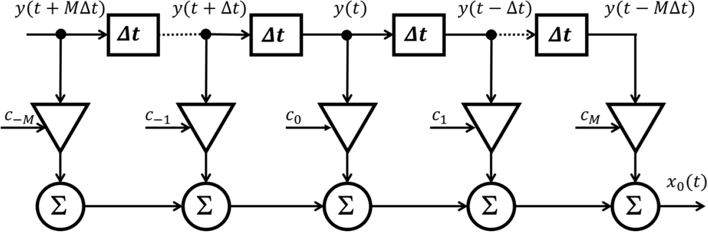
The FIR filter model described by Meltenisov includes 2M + 1 coefficients cn obtained from Eq. (12), and is inherently non-causal, as it relies on both past and future components of the signal. A schematic representation of this filter is shown in Fig. 2.
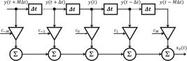
As discussed in Subsection II-C, a causal approximation of this filter can be constructed by removing the non-causal terms, enabling physical implementation using passive optical systems such as the photonic perceptron. An alternative approach, presented later in Subsection II-D, preserves all coefficients by temporally shifting the non-causal components until they become fully causal, yielding a time-shifted symmetric formulation that maintains the frequency characteristics of the original filter while ensuring realizability.
C. Formal Association between the Passive Perceptron and the Causal FIR Filter
This section establishes the mapping between the analytically derived FIR filter coefficients and the physical parameters of the photonic perceptron, reinforcing its role as a hardware implementation of the filter rather than as an independent computational model.
Based on the information provided in Subsections II-A and II-B, and extending the preliminary analysis in [14], the transfer function in Eq. (13) can be shown to be structurally similar to that of the perceptron model, provided that the same time interval Δt is used in both expressions. This similarity arises because both transfer functions are designed for CDC.
To enable direct comparison, Eq. (13) is rewritten using a backward-looking delay representation, as suggested in [15]:
Comparing Eq. (14) and Eq. (9), we observe that both models share a common structure when operating with the same delay interval ∆t. As discussed in Section III, is asymmetric with respect to due to its truncated causal series with . Nevertheless, preliminary simulation results indicate that , when properly matched to the signal bandwidth, can still achieve effective chromatic dispersion compensation. To construct a causal approximation of , we define
Adopting M = N - 1 and n = k - to align the indices and the number of harmonics with the perceptron model, and expressing each coefficient ck - 1 in polar form, Eq. (15) yields the following causal expression:
To physically implement the response in Eq. (16), each optical path must provide both phase shifts and adjustable attenuation to reproduce the magnitudes |ck - 1. In practice, this requires the inclusion of tunable attenuators in addition to the intrinsic losses of the delay lines. A global normalization factor can then ensure that all coefficients remain within passive limits, avoiding the need for optical amplification. The detailed implementation method is presented in Section II-D.
Comparing Eq. (16) and Eq. (9), we observe that the perceptron’s hardware can emulate the phase response of the FIR filter when , even if . This approximation enables effective dispersion compensation despite the amplitude mismatch, since phase alignment plays a dominant role in CDC under linear optical regimes. Therefore, to make the two equations equivalent, an amplitude error e(k) must be introduced such that . This error term was implicitly minimized by Mancinelli [10] during hardware tests for various Δt values, acknowledging that these results constitute an approximation, since the impact of such mismatches will be addressed in future work.
To explicitly represent this approximation, we define a transfer function , which describes the practical behavior of the optical perceptron using the actual attenuation values ak, as implemented in the hardware, combined with the analytically calculated phases θk - 1 derived from the Fourier coefficients:
This function captures the joint effect of the fixed attenuation profile from Mancinelli’s implementation [10] and the spectral phase structure obtained from Meltenisov’s analytical model [11]. Although this approach introduces a mismatch in amplitude, it aligns the spectral phase correctly, thereby achieving satisfactory dispersion compensation across a useful transmission range. This observation is further supported by simulations, which show that the waveform synthesized by closely resembles the target FIR response in terms of phase behavior, confirming that the relative phase contributions dominate the system response under the assumed conditions.
D. Time-Shifted Symmetric FIR Filter
This section investigates a modified perceptron architecture in which optical paths are equipped with tunable attenuators. These attenuators reproduce the modulus of the symmetrically shifted coefficients |cn - M.
The frequency response in Eq. (14) is symmetric and mathematically valid; however, it cannot be directly implemented in real-time systems because it includes non-causal terms, that is, coefficients associated with negative indices. To overcome this limitation, a time shift is applied to the filter, displacing the index range from n=-M to M into a purely non-negative domain, n=0 to 2M. This operation is equivalent to delaying the entire impulse response by M steps, thus yielding a causal version of the filter:
This causal formulation preserves the frequency characteristics of the original filter, while enabling physical implementation using only delay elements. The term cn - M ensures that the coefficients retain their original symmetry about n=M.
To implement the causal FIR filter described by Eq. (18) without relying on optical amplifiers, it is necessary to compensate for the natural attenuation profile of the spiral waveguides, defined by Eq. (4) and assumed to be monotonically decreasing with n due to the longer optical paths. The amplitude profile of the filter must therefore reproduce the modulus of the coefficients cn - M, which represent the ideal contribution of each delayed path and ensure that the causal response maintains the desired symmetry. To achieve this, each optical branch must include a mechanism that transforms the intrinsic attenuation an into the target amplitude |cn - M, requiring a compensatory gain defined as:
where An is the required gain for the n-th branch.
Since the architecture relies on passive optical paths equipped with tunable attenuators, which can only impose variable loss, the overall gain must be normalized to ensure that all values remain less than or equal to one. This normalization, derived from Eq. (19), is achieved by decomposing the gain into two factors: a normalized attenuation coefficient Ân, applied by the attenuator, and a global gain factor g0, applied externally to compensate for the maximum required gain:
where .
Accordingly, the frequency response of the implemented causal filter becomes:
where the product ensures the desired amplitude contribution in each delayed path while maintaining the passive nature of the system.
III. SIMULATION SETUP AND EVALUATION METHODOLOGY
Simulation scenarios were developed to validate the proposed analytical FIR design method and its implementation using the photonic perceptron hardware platform. The optical communication system was modeled using Ansys Lumerical INTERCONNECT® and employed non-return-to-zero (NRZ) on-off keying (OOK) signals transmitted over standard single-mode fiber (SSMF). Bit rates were swept from 6.25 Gbps to 40 Gbps in increments of 1.25 Gbps. Two distinct delay configurations were considered in the photonic FIR filter: ∆t =25 ps and ∆t =50 ps.
The delay values were chosen based on typical parameters reported for photonic integrated FIR filters and interferometric mesh structures. A delay of 50 ps is commonly adopted in optical FIR implementations, while 25 ps represents a practical lower bound considering propagation losses and power budget constraints in passive silicon photonic platforms. Smaller delays would require additional optical amplification to compensate for losses in each delay branch, thereby increasing system complexity and deviating from a fully passive implementation.
Since the free spectral range (FSR) of the FIR filter is inversely proportional to the delay,
these delay values also allow the evaluation of the filter response under different spectral periodicities and dispersion compensation ranges.
The bit-rate range was defined as multiples of 6.25 Gbps, corresponding to a submultiple of 25 Gbps. This rate is widely adopted in modern communication systems, particularly in single-lane Ethernet standards such as IEEE 802.3by, which specifies 25 Gbps operation over both electrical and optical physical layer implementations [16]. In optical links, this data rate is commonly associated with IMDD using two-level signaling formats consistent with NRZ transmission.
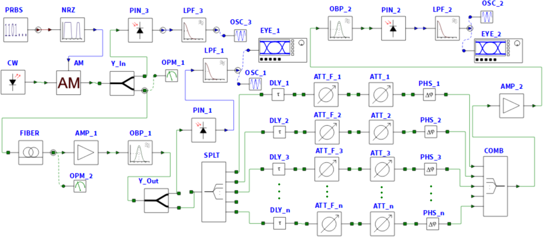
The simulated system, depicted in Fig. 3, employs a continuous-wave (CW) laser at 1552.5 nm modulated using NRZ-OOK and driven by a 4096-bit pseudo-random bit sequence (PRBS) with balanced logical levels. The optical signal is then processed by the photonic filter, which consists of a power splitter, multiple delay lines, programmable attenuators, and phase shifters. After photodetection and low-pass filtering, the output is evaluated using an eye diagram analyzer to assess the performance of dispersion compensation. In this model, each attenuator is represented by an ideal attenuation block ATT_n from the INTERCONNECT library.
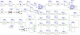
Post-compensated optical system modeled in the INTERCONNECT® simulator. The AM block emulates the behavior of a Mach-Zehnder modulator.
Three representative implementation scenarios were considered to evaluate the influence of amplitude control and spectral truncation on dispersion compensation performance.
In the first scenario (S1), defined by Eq. (17), the perceptron operates in a fully passive configuration using only delay lines and phase shifters. In this case, the amplitude profile of each optical path is dictated by the intrinsic attenuation of the spiral waveguides, such that only the phase of the Fourier coefficients is effectively implemented. As a result, an amplitude mismatch is introduced, which is not explicitly compensated and is expected to limit performance, particularly at higher bit rates. Nevertheless, this scenario highlights the dominant role of phase information in chromatic dispersion compensation.
In the second scenario (S2), described by Eq. (16), tunable attenuators are incorporated to enable independent control of both amplitude and phase, following the approach in [17]. The Fourier magnitudes are normalized with respect to the intrinsic losses of the delay lines and mapped onto the attenuators, while a global normalization factor g0 is applied externally. This configuration eliminates the amplitude mismatch observed in S1 and provides a more accurate realization of the truncated causal FIR response, without requiring optical gain within the filter arms.
Finally, the third scenario (S3) extends S2 by incorporating the full set of Fourier coefficients through a time-shifted symmetric formulation, as given by Eq. (20). By shifting the spectrum to obtain a causal implementation, this approach preserves the original symmetry of the coefficients and avoids truncation effects. Consequently, it achieves a closer approximation to the ideal analytical response and improved performance at higher bit rates, while maintaining the same amplitude control strategy adopted in S2.
To establish a direct correspondence between the simulated photonic filter and its analytical modeling, the blocks ATT_I_n represent the intrinsic, non-programmable spiral attenuations an, while the delay blocks DLY_n implement the multiple time delays n∆t introduced by the spirals. In addition, the phase-control blocks PHS_n represent the phase terms θ associated with the Fourier-based complex coefficients. For Scenarios S2 and S3, the blocks ATT_n implement the normalized magnitudes Ân of the Fourier coefficients and the amplifier AMP_2 implements the global gain factor g0, whereas in Scenario S1 both ATT_n and AMP_2 are set to 0 dB, ensuring a purely phase-based realization.
Chromatic dispersion compensation performance was evaluated under identical simulation conditions for all configurations, including both the original perceptron model and the modified architecture with programmable attenuators. The analysis was conducted in the presence of amplified spontaneous emission (ASE) noise from an erbium-doped fiber amplifier (EDFA), while optical nonlinearities were neglected.
The simulation used INTERCONNECT’s built-in EYE_n analyzer blocks to evaluate the eye diagrams. Performance evaluation was based on the Q factor, measured in the center of each transmitted bit, as defined in the Ansys documentation [18]. The bit error rate (BER) for a given Q factor was estimated using the expression [19]:
The analytical method was validated through simulations, where FIR filter coefficients were applied to different system configurations. The configurations included truncated Fourier spectra as well as time-shifted symmetric spectra. The effectiveness of chromatic dispersion compensation was evaluated using eye diagram quality and the corresponding bit error rate (BER) estimates. The next section presents the results and analyzes the impact of delay spacing and the number of filter ports on overall system performance.
IV. RESULTS AND DISCUSSION
The results obtained through simulations performed in the INTERCONNECT environment are presented. The simulator was used to evaluate the behavior of the NRZ-OOK optical signal using a PRBS over a single-mode fiber link. The analysis emphasizes the role of phase in CDC, while also evaluating the impact of amplitude control through different implementation scenarios.
The transmission link consists of 100~km of SSMF. The fiber parameters used in the simulations were attenuation and chromatic dispersion at the operating wavelength of 1552.5 nm. The total accumulated chromatic dispersion over the link is approximately 1770 ps/nm. This transmission distance was selected to represent LR-PON scenarios, typically ranging from 20 km to 100 km, where chromatic dispersion significantly degrades IMDD system performance and dispersion compensation becomes necessary. Polarization mode dispersion and nonlinear effects were not considered, since the analysis focuses on chromatic dispersion compensation in IMDD systems.
Although the time spacing ∆t =50 ps and ∆t =25 ps theoretically support NRZ bit rates of up to 20 Gbps and 40 Gbps, respectively, achieving these rates depends on the availability of a sufficient number of filter coefficients.
As demonstrated by Meltenisov [20], a minimum number of coefficients is required to ensure effective dispersion compensation, which constrains the achievable bit rate for a given value of ∆t. This requirement can be formally expressed by Eq. (22), which indicates a quadratic dependence between the signal bandwidth and the filter order.
where is the total range of normalized delays (in discrete-time units defined by ∆t, and fH and fL are the upper and lower frequencies of the signal bandwidth, respectively.
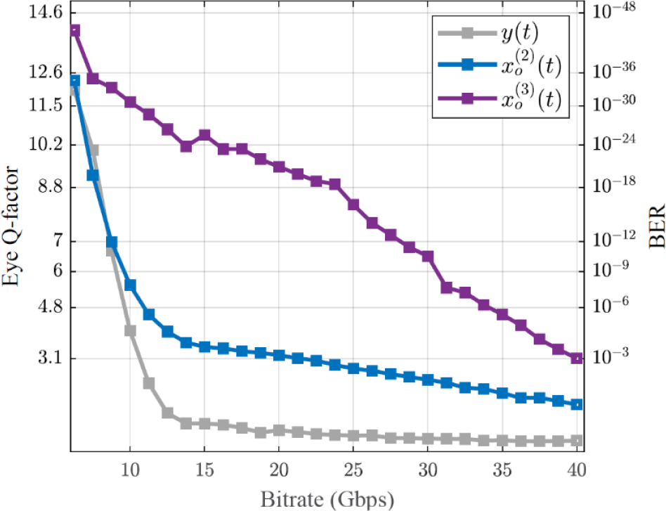
In all eye-diagram analyses presented in Figs. 4-6, the estimated BER values were calculated from the corresponding Q-factor using Eq. (21).
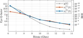
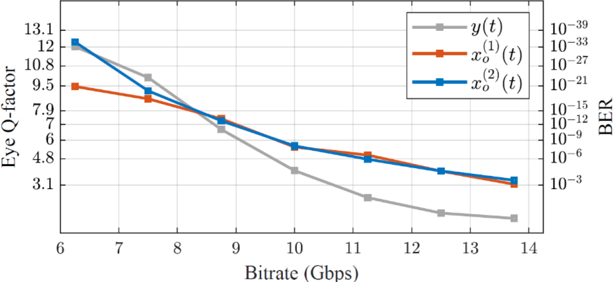
Eye diagram metrics for N=4 and ∆t =50 ps comparing scenarios S1 and S2, showing Q factor and the corresponding BER.

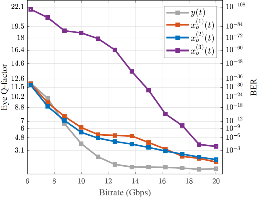
Eye diagram metrics for N=7 and ∆t=50 ps using three compensation strategies: scenario S1, scenario S2, and scenario S3. The curves show Q factor and the corresponding BER.
Fig. 4 reports the Q factor and the estimated BER for the case with N=4 and delay spacing ∆t =50 ps.
Two implementations are compared: scenario S1, which applies phase-only compensation using the intrinsic attenuation profile of the spiral waveguides, and scenario S2, which reproduces the truncated Fourier coefficients, including both amplitude and phase. In all eye-diagram figures, the estimated BER is indicated on the right-hand vertical axis for direct comparison with the Q factor.
Fig. 5 shows the results for N=7 with delay spacing ∆t =50 ps, where the three scenarios S1, S2, and S3 are compared. The corresponding curves highlight the differences in compensation performance.
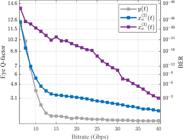
Eye diagram metrics for N=23 and ∆t =25 ps using two compensation strategies: scenario S2 and scenario S3.
In contrast, Fig. 6 presents the case with N=23 and reduced spacing ∆t =25 ps, where only scenarios S2 and S3 are included.
Quantitatively, using NRZ OOK over a 100 km SSMF link and including ASE noise, the configuration with N=4 and ∆t =50 ps sustained BER<10-3 up to 13.75 Gbps with the S1 formulation and up to 15 Gbps with the S2 formulation, as shown in Fig. 4. For N=7 at ∆t =50 ps, the system reached 16.25 Gbps for both S1 and S2, and 20 Gbps for S3, as shown in Fig. 5. For the larger setup with N=23 and ∆t =25 ps, the system achieved 22.5 Gbps with S2 and up to 40 Gbps with S3, as shown in Fig. 6. The S1 case was not further investigated because of its limited performance under these conditions. These results are illustrative rather than absolute performance limits and confirm that increasing the number of optical paths and employing symmetrically shifted coefficients can extend the feasible bit rate. However, this improvement introduces trade-offs associated with accumulated loss and the opening of the eye diagram.
The curves show Q factor and the corresponding BER.
Another advantage of the proposed approach is that it does not require weight determination and the consequent adjustment of the thermal modulator setup when the NRZ signal transmission rate changes, because this rate is not involved in the calculation of the FIR filter coefficients.
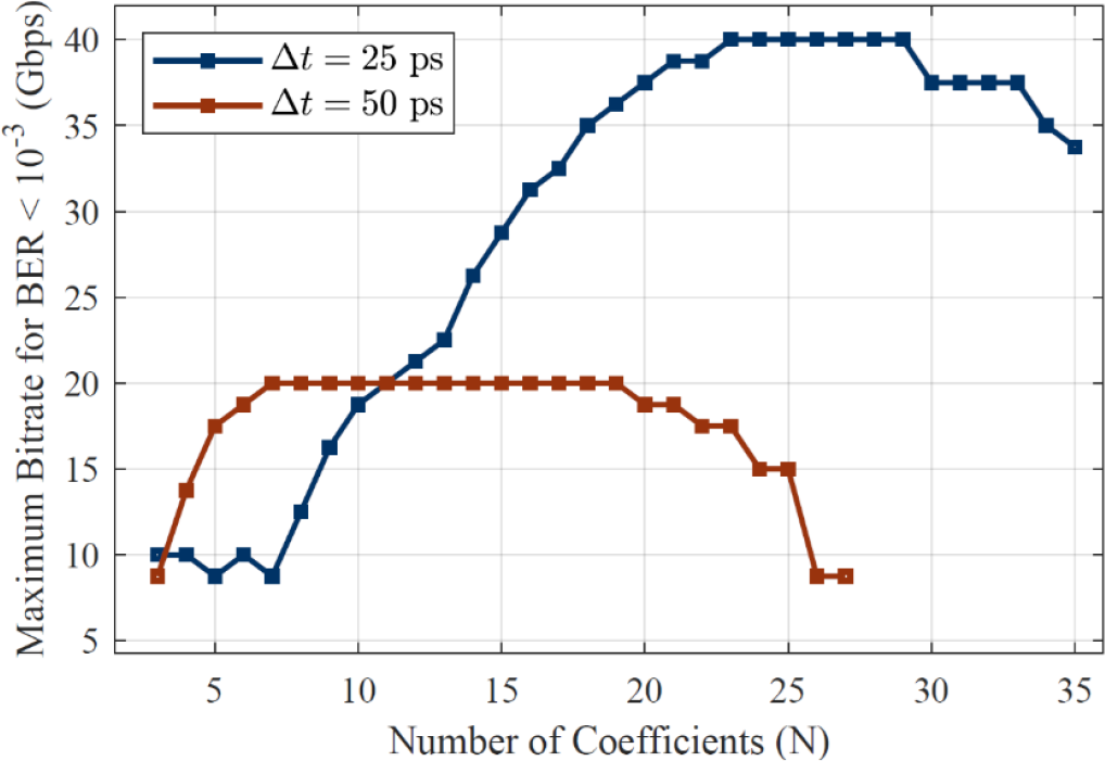
Fig. 7 summarizes the estimated maximum data rates achievable with BER<10-3, which corresponds to a Q factor of approximately 3.0901, for varying numbers of coefficients N, using the time-shifted causal FIR implementation of scenario S3 described in Subsection II-D, and considering two delay spacings of ∆t =25 ps and ∆t =50 ps.
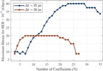
Estimated maximum bit rate for BER<10-3 as a function of the number of filter coefficients N, for two delay spacings ∆t =25 ps and ∆t =50 ps, obtained with the time-shifted causal FIR filter of scenario S3.
In the simulations, the optical attenuators exhibited a maximum attenuation of approximately 20 dB for ∆t =50 ps with N=7, and about 30 dB for ∆t =25 ps with N=23, consistent with the expected increase in optical path imbalance and corresponding amplitude weighting requirements.
This degradation arises not only from the cumulative attenuation imposed by the filtering architecture, but also from the reduction in signal-to-noise ratio caused by the global normalization factor g0. While g0 ensures passive operation, it uniformly reduces the effective signal power at the output, an effect that becomes more pronounced for large N, ultimately degrading the achievable transmission rate.
Although scenario S₃ achieves superior performance compared to the other configurations, it exhibits stronger attenuation as the number of coefficients N increases. This behavior may impose a practical limitation for implementations targeting very high data rates, since the cumulative loss becomes more significant in architectures with a large number of optical paths.
V. CONCLUSION AND FUTURE WORK
This work presented a closed-form analytical framework for designing optical FIR filters for chromatic dispersion compensation using a photonic perceptron as the implementation platform. By leveraging a Fourier-series-based synthesis, the method enables direct mapping of the compensation function onto the parameters of the optical hardware, avoiding iterative optimization and adaptive processing.
The results show that phase-only implementations (S1) are effective at lower data rates, while configurations incorporating amplitude control (S2 and S3) significantly enhance performance. Among them, the time-shifted symmetric formulation (S3) achieves the best results, particularly at higher bit rates.
These findings demonstrate that dispersion compensation can be efficiently realized using analytically derived coefficients in passive photonic hardware, making the approach suitable for next-generation LR-PON systems requiring extended reach, higher data rates, and energy-efficient operation.
Future work will investigate the impact of amplitude mismatches between optical paths, particularly in phase-only configurations such as S1, where the amplitude profile is constrained by intrinsic attenuation. In parallel, further research will focus on architectures capable of supporting higher data rates through time-shifted FIR formulations, as in S3, which preserve spectral symmetry and may require an increased number of delay elements according to Eq. (22).
In addition, attenuation mitigation in large-scale implementations remains an important challenge. Although this work focuses on fully passive silicon-integrable solutions, hybrid approaches incorporating semiconductor optical amplifiers (SOAs) may help restore the desired amplitude profile and improve scalability.
Finally, experimental validation using photonic integrated circuits (PICs) will be essential to assess the practical performance and robustness of the proposed approach under realistic conditions.
ACKNOWLEDGMENTS
This work was supported by the Fundação de Amparo à Pesquisa e Inovação do Espírito Santo (FAPES) under grant 361/2023, and by the Conselho Nacional de Desenvolvimento Científico e Tecnológico (CNPq) under grants 309082/2020-0 and 440227/2021-6.
Additional support was provided through the CNPq-FAPES cooperation agreement, grant CNPq/FAPES 2025 n° 1032/2025, P: 2025-BBCW2.
DATA AVAILABILITY
The data that support the findings of this study are available at: https://doi.org/10.5281/zenodo.20077602
REFERENCES
-
[1] A. Haastrup, M. Zehri, D. Rincón, J. R. Piney and A. Bazzi, "A distance-weighted dynamic bandwidth allocation algorithm for improved performance in long-reach passive optical networks for Next Generation Networks," Photonics, vol. 10, no. 8, pp. 923:1-923:21, 2023, DOI:10.3390/photonics10080923.
» https://doi.org/10.3390/photonics10080923. -
[2] L. Grüner-Nielsen, M. Wandel, P. Kristensen, C. G. Jørgensen, L. V. Jørgensen, B. Edvold, B. Pálsdóttir and D. Jakobsen, "Dispersion-compensating fibers," Journal of Lightwave Technology, vol. 23, no. 11, pp. 3566-3579, 2005, DOI:10.1109/JLT.2005.855873.
» https://doi.org/10.1109/JLT.2005.855873. -
[3] K. S. S. Liyakat and K. K. S. Liyakat, "Dispersion compensation in optical fiber: A review," Journal of Telecommunication Study, vol. 8, no. 3, pp. 1-12, 2023, DOI:10.46610/JTC.2023.v08i03.001.
» https://doi.org/10.46610/JTC.2023.v08i03.001. - [4] J. Capmany and D. Pérez, Programmable Integrated Photonics, Oxford, UK: Oxford University Press, 2020.
- [5] A. Rahim, S. Schwarz, J. Bruns, K. Voigt, D. I. Kroushkov, M. T. Arnous, L. Zimmermann, C. G. Schäffer, and K. Petermann, “Tunable residual dispersion compensator using generalized MZIs in silicon-on-insulator,” in OFC/NFOEC, pp. 1-3, 2012.
-
[6] X. Liu, G. Ren, X. Xu, A. Dubey, T. Feleppa, A. Boes, A. Mitchell, and A. Lowery, “Adaptive dispersion compensation using a photonic integrated circuit finite impulse response filter,” Optics Express, vol. 31, no. 22, pp. 35 971-35 981, 2023, DOI:10.1364/OE.496387
» https://doi.org/10.1364/OE.496387 -
[7] X. Huang, F. Xie, W. Zuo, and Y. Qiao, “Multi-tap optical delay line-based optical-electrical dispersion compensation scheme in high-speed im/dd systems,” Journal of Lightwave Technology, vol. 43, no. 2, pp. 450-462, 2024, DOI:10.1109/JLT.2024.3457882
» https://doi.org/10.1109/JLT.2024.3457882 -
[8] S. Lang, Y. Liu, Z. Bai, Z. Ge, H. Du, and T. Li, “An on-chip tunable dispersion compensator based on 8th-order FIR architecture,” 2025 Asia Communications and Photonics Conference (ACP), pp. 1-3, 2025, DOI:10.1109/ACP66871.2025.11349927.
» https://doi.org/10.1109/ACP66871.2025.11349927. -
[9] Z. Hui, B. Xian, D. Han, T. Li, and A.-H. Soliman, “Integrated dispersion compensator based on cascaded silicon micro-ring resonators,” Optics Express, vol. 33, no. 8, pp. 16 778-16 794, 2025, DOI:10.1364/OE.554967
» https://doi.org/10.1364/OE.554967 -
[10] M. Mancinelli, D. Bazzanella, P. Bettotti and L. Pavesi, "A photonic complex perceptron for ultrafast data processing," Scientific Reports, vol. 12, no. 1, p. 4216:1-4216:11, 2022, DOI:10.1038/s41598-022-08087-2.
» https://doi.org/10.1038/s41598-022-08087-2. -
[11] M. Meltenisov and A. Matukhin, "Optical filters for adaptive compensation of chromatic dispersion in high-speed optical transmission systems," 2016 8th International Congress on Ultra Modern Telecommunications and Control Systems and Workshops (ICUMT), Lisbon, Portugal, pp. 62-66, 2016, DOI:10.1109/ICUMT.2016.7765333.
» https://doi.org/10.1109/ICUMT.2016.7765333. - [12] G. P. Agrawal, Nonlinear Fiber Optics, 5th ed., Oxford, UK: Academic Press, 2013.
-
[13] M. Meltenisov and A. Matukhin, "Analytical model of chromatic dispersion effect in the time domain," 2016 18th International Conference on Advanced Communication Technology (ICACT), PyeongChang, South Korea, pp. 406-409, 2016, DOI:10.1109/ICACT.2016.7423410.
» https://doi.org/10.1109/ICACT.2016.7423410. -
[14] A. P. Togneri, M. E. V. Segatto and R. B. Nunes, "Analytical determination of phase weights in a time-delayed photonic neural network for dispersion compensation," 2025 21st SBMO/IEEE MTT-S International Microwave and Optoelectronics Conference (IMOC), Campina Grande, Brazil, pp. 1-5, 2025, DOI:10.1109/IMOC65414.2025.11365889.
» https://doi.org/10.1109/IMOC65414.2025.11365889. - [15] B. P. Lathi and R. A. Green, Linear Systems and Signals, 2nd ed., New York, USA: Oxford University Press, 2005.
- [16] IEEE Standard for Ethernet-Amendment 2: Physical Layers for 25 Gb/s Operation, IEEE Std. 802.3by-2016, 2016.
-
[17] P. R. N. Marciano, E. Staffoli, J. A. L. Silva, G. Maddinelli, M. J. Pontes, M. S. Coelho, L. C. B. Silva, M. E. V. Segatto and L. Pavesi, "Chromatic distortion precompensation in OFDM-based optical systems through an integrated silicon photonic neural network," Journal of Lightwave Technology, vol. 43, no. 7, pp. 3034-3040, 2025, DOI:10.1109/JLT.2024.3511993.
» https://doi.org/10.1109/JLT.2024.3511993. -
[18] Ansys Inc., “Eye diagram (eye) - interconnect element,” Ansys Lumerical Documentation, 2023, online; accessed 2025-05-06. [Online]. Available: https://optics.ansys.com/hc/en-us/articles/360036107074-eye-diagram-eye-interconnect-element
» https://optics.ansys.com/hc/en-us/articles/360036107074-eye-diagram-eye-interconnect-element -
[19] B. Nebendahl, R. Schmogrow, T. Dennis, A. Josten, D. Hillerkuss, S. Koenig, J. Meyer, M. Dreschmann, M. Winter, M. Huebner, W. Freude, C. Koos, and J. Leuthold, “Quality metrics in optical modulation analysis: EVM and its relation to Q-factor, OSNR, and BER,” Asia Communications and Photonics Conference (ACP), pp. 1-3, 2012, DOI:10.1364/ACPC.2012.AF3G.2.
» https://doi.org/10.1364/ACPC.2012.AF3G.2. -
[20] M. Meltenisov and A. Matukhin, "Estimation of minimum required number of coefficients of digital filter for chromatic dispersion compensation in optical fiber," 2018 10th International Congress on Ultra Modern Telecommunications and Control Systems and Workshops (ICUMT), Moscow, Russia, pp. 1-4, 2018, DOI:10.1109/ICUMT.2018.8631259.
» https://doi.org/10.1109/ICUMT.2018.8631259.
-
Editor:
Carlos E. Capovilla
-
Associate Editor:
Karcius D. R. Assis