A Triple Band Frequency Selective Surface with Low Insertion Loss, Angular Stability and Polarization Independence
Abstract
This paper presents the design and experimental validation of a compact, single-layer, triple-band Frequency Selective Surface (FSS) based on triple square loops. The proposed structure targets resonant frequencies at 1.56 GHz, 2.45 GHz, and 3.50 GHz, corresponding to the GPS L1, Wi-Fi, and 5G bands, respectively. An equivalent circuit model (ECM) was developed to guide the initial parametric design, reducing reliance on computationally intensive full-wave simulations. The structure was optimized using HFSS and fabricated on a low-cost FR-4 substrate. Simulated and measured results show good agreement, with three well-defined stop bands exhibiting low insertion loss and stable resonant frequencies. Experimental measurements under oblique incidence up to 45° confirm the angular stability of the design for both TE and TM polarizations. Compared to prior works, the proposed FSS offers simpler geometry, lower fabrication complexity, closely spaced resonances with minimal frequency shift under angular variation, and low pass-band insertion losses. These features make the proposed FSS a strong candidate for compact and low-profile solutions in GPS, Wi-Fi, and 5G systems requiring multiband electromagnetic filtering.
Index Terms
Triple-band; equivalent circuit model; angular stability; polarization independence.
I. INTRODUCTION
Frequency Selective Surfaces (FSS) are spatial filters formed by periodic arrays of identical metallic elements printed on dielectric substrates [1]. Their electromagnetic behavior can be tailored to selectively reflect or transmit specific frequency bands, depending on the geometry of the elements: patch-type structures typically operate as band-stop filters, while aperture-type structures function as band-pass filters [2].
Due to their versatility, Frequency Selective Surfaces (FSSs) are widely employed in various applications, including antenna reflectors [3]-[5], electromagnetic lenses [6], absorbers [7]-[10], polarization converters [11], and randoms [12] and [13]. They can also be integrated with antennas to enable miniaturization or enhance system gain [9], [14]-[15]. Additionally, FSSs serve as effective spatial filters for electromagnetic waves [16]-[18] and have been explored for use in sensor systems [19], [20].
Certain applications demand triband FSSs, and several studies have proposed structures exhibiting a triband frequency response [21]-[24]. However, many of these designs suffer from insertion losses exceeding 2 dB within the pass bands or rely on highly complex geometries. In addition to these limitations, angular stability and polarization independence are critical performance factors that must also be considered in practical implementations.
Numerous studies have been conducted to develop triband FSSs with desirable performance characteristics [21]-[29]. While these works demonstrate triband responses, most fail to simultaneously achieve key attributes, such as angular stability, polarization independence, geometric simplicity, and low insertion loss within the passbands, among other essential features.
In [21], the authors explored the use of hexagonal convoluted structures for 5G mobile communication applications, using an FR-4 substrate (εr = 4.4). The proposed FSS exhibited band-stop behavior, with resonances at 2.8, 3.46, and 4.11 GHz, characterizing a closely spaced triband response with a frequency ratio below 2. While the design demonstrated to be stable under oblique incidence and insensitive to polarization, it suffered from high geometric complexity and insertion losses exceeding 2 dB within the pass bands.
In [22], a triband FSS based on textile material was proposed for 5G millimeter-wave applications, employing a cotton textile substrate with a relative permittivity (εr) of 1.6. The unit cell geometry comprised three concentric circular rings, with the innermost ring featuring a pair of cross-shaped stubs. The structure exhibited band-stop behavior, resonating at 24, 37, and 46 GHz. However, the design was geometrically complex and showed insertion losses exceeding 2 dB. Additionally, the study did not include experimental validation, limiting the assessment of its practical performance.
In [23], a 2.5D triband FSS was proposed for electromagnetic shielding in sub-6 GHz bands, specifically targeting NR n46, LTE 42/43, and LTE 46. The structure features spiral-shaped meander lines etched on both sides of an FR4 substrate and εr = 4.4, interconnected by four edge vias that increase the effective electrical length. The unit cell exhibits 90° rotational symmetry, resulting in a miniaturized, polarization-independent geometry. The FSS resonates at 2.6 GHz, 3.62 GHz, and 5.6 GHz, with angular stability up to 60°. However, the design remains geometrically complex and shows insertion losses exceeding 3 dB in the pass bands.
In [24], the authors proposed a multiband FSS with high selectivity, designed for microwave communication and stealth radar applications. The structure is composed of three periodic metallic layers, separated by dielectric substrates (Rogers RO4350B and εr = 3.48) and PMI foam. The top and bottom layers incorporate circular rings and convoluted square turns, while the middle layer features complementary patterns to those on the outer layers. The FSS exhibits three pass bands, 2.79 - 4.79 GHz, 7.77 - 8.91 GHz, and 11.29 - 13.75 GHz, with bandwidths exceeding 1 GHz, along with angular stability up to 50°, polarization independence, and low insertion loss. However, the design suffers from significant volume and high fabrication complexity, which may limit its practical implementation.
In [25], the authors proposed a multifunctional FSS to operate under wide incidence angles. The structure features pixel-based double layers and targets applications in the X, K, and Ka bands. It is implemented using copper metallic layers separated by a foam substrate with relative permittivity εr = 3.2. Simulation results show attenuation greater than -15 dB across the entire X band with two pass bands in the K and Ka bands, offering bandwidths of approximately 3.56 GHz and 3.15 GHz, respectively. The FSS demonstrated a stable frequency response for incidence angles up to 45°. However, the design is characterized by substantial volume and high fabrication complexity, which may pose challenges for practical deployment.
In [26], the authors proposed a novel FSS unit cell comprising three elements: a crossed dipole, a set of square rings with slots positioned at the ends of the dipole, and an outer square loop enclosing the other components, fabricated on an RT5880 substrate with a relative permittivity (εr) of 2.2. Simulation results showed that the FSS operates as a band-stop filter, with resonances at 3.24 GHz, 6.08 GHz, and 10.88 GHz, corresponding to the S, C, and X bands, respectively. These resonances are considered closely spaced, exhibiting frequency ratios below 2. The design demonstrated a stable frequency response up to 45° incidence for the first two bands, though stability decreased at the third resonance. Additionally, the structure features high fabrication complexity.
In [27], a multiband FSS composed entirely of metal was proposed, with the prototype fabricated using laser cutting. The unit cells are arranged in a 2×2 configuration, each consisting of slotted square turns rotated by 90° relative to adjacent cells. The FSS was designed to operate at resonant frequencies of 5.67 GHz, 9.04 GHz, and 10.47 GHz, which are closely spaced, with insertion losses lower than 1.4 dB. The design demonstrated polarization insensitivity and maintained stable performance for incidence angles up to 30°.
In [28], the authors proposed a new frequency-selective surface featuring a miniaturized 2D unit cell with a convoluted geometry, aimed at wireless communication applications. The structure was fabricated on an FR-4 substrate with a relative permittivity (εr) of 4.4 and designed to block frequency bands at 1.6 GHz, 2.4 GHz, and 5.1 GHz. The FSS demonstrated angular stability up to 70°, with frequency deviation below 1%. However, the design exhibits high insertion losses beyond 45° incidence and involves complex geometry. Additionally, the ratio between the third and second resonances exceeds 2, indicating that these resonances are not closely spaced.
Another triband complementary frequency selective surface (CFSS) with very closely spaced bands and strong angular stability was proposed in [29]. The CFSS unit cell consists of double concentric rings, chosen specifically for their excellent angular stability, implemented on an FR-4 substrate (εr = 4.4). The resonance frequencies achieved were 2.09 GHz, 2.49 GHz, and 2.66 GHz, made possible by the complementary nature of the design. Despite the closely spaced resonances, the structure exhibited insertion losses exceeding 5 dB.
In this work, we propose a single-layer FSS with a simple unit cell geometry based on triple square turns. To support the design process, an equivalent circuit model was developed to enable fast parametric analysis, greatly simplifying the initial design and optimization stages and reducing reliance on computationally intensive electromagnetic simulations. Following the parametric study, the FSS was optimized using HFSS, fabricated, and experimentally validated. The resulting structure meets all the desired performance criteria: compact size, ease of fabrication, angular stability, polarization independence, low insertion loss in the pass bands, and suitability for triband applications.
II. EQUIVALENT CIRCUIT MODEL
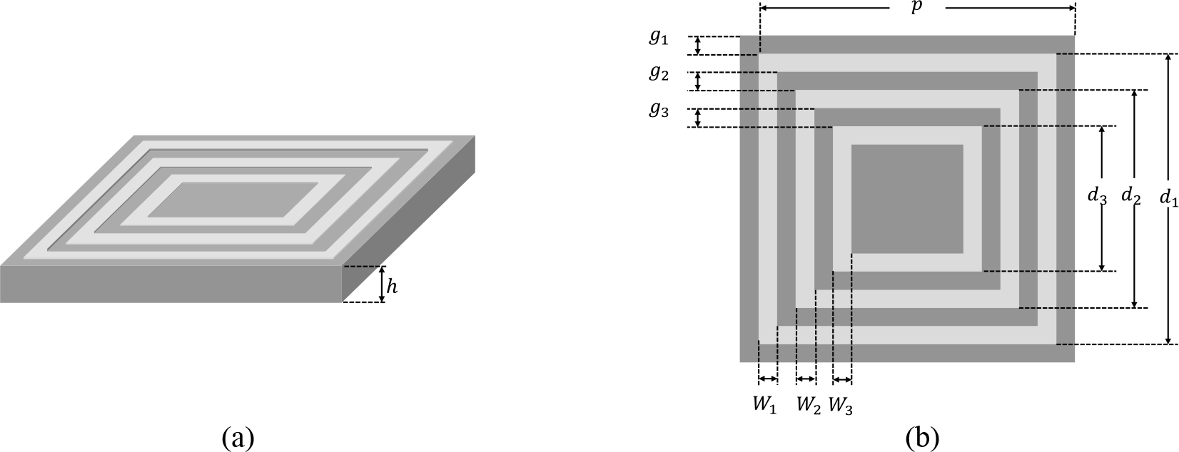
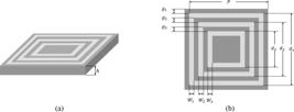
The Frequency Selective Surface (FSS) based on triple square loops is a relatively simple structure implemented on a dielectric substrate [30]. In the Equivalent Circuit Method (ECM), the structure is typically assumed to have infinite periodic extension. Fig. 1 (a) and (b) illustrate the geometry and physical parameters of a unit cell within the array.
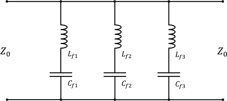
The admittance of the FSS depends on the specific geometry used in the design. In this case, the triple-square loop is modeled using the equivalent circuit approach, shown in Fig. 2.
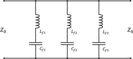
For transverse electrical (TE) wave incidence, the vertical strips act as an L impedance, and the horizontal strips as a C impedance [31], [32]. The basic equations for calculating the values of inductance and capacitance are found in Marcuvitz [33] and are given, for normal incidence, in general form by:
where,
The equivalent circuit modeling for the FSS with triple square loops starts with the FSS circuit with double square loops, inserting a third smaller turn. Thus, of the six elements of the equivalent circuit in Fig. 2, four are derived from the FSS circuit with double square loops, as follows:
where,
The inner loop inserts a third branch into the equivalent circuit, whose components are calculated as:
where,
In the analytical expressions for inductance and capacitance, the scaling coefficients appearing in (9), (10), (16), and (17) are empirically tuned parameters. They are adopted and used to account for higher-order coupling effects, finite strip width corrections, and non-ideal current distributions that are not fully captured by the basic quasi-static expressions.
The factor εeff presents in the equations (9), (10), and (17), was introduced in [34] and it is calculated as:
where x = 10h/p and N is an exponential factor, which depends on the modeled geometry and the amount of metal in the unit cell [34].
In the proposed equivalent circuit model, the metallic scatterer is assumed to be a perfect electric conductor (PEC). Therefore, ohmic (conductor) losses are neglected, and only the dominant reactive behavior is considered. The effect of losses is implicitly captured in the full-wave simulations and experimental results, where finite conductivity and dielectric losses are naturally included.
A. Parametric analysis
The proposed FSS is based on triple square loops, a well-established geometry known for its robust angular response and polarization-independent behavior. The structure is designed to resonate at 1.56 GHz (GPS L1 band), 2.45 GHz (Wi-Fi band), and 3.50 GHz (5G band). The chosen dielectric substrate is FR-4, with a thickness of 1.6 mm, relative permittivity (ɛεr) of 4.4, and a loss tangent of 0.02. The FSS consists of a single-layer configuration on a thin substrate, with N-value of 1.2.
To determine the physical dimensions that yield the desired frequency response, a parametric analysis was conducted on the unit cell element dimensions: d1, d2, d3, w1, w2 and w3. The periodicity was set to p = 29 mm, a value selected to prevent the appearance of grating lobes. Each loop’s physical size significantly affects its corresponding resonance frequency. For instance, the outermost and largest loop predominantly influences the 1.56 GHz resonance. The analysis uses a MATLAB routine implementing the equivalent circuit method, as described in the previous section. Considering manufacturing constraints, the ribbon widths and loop lengths were varied to identify dimensions that produced resonances at the target frequencies.
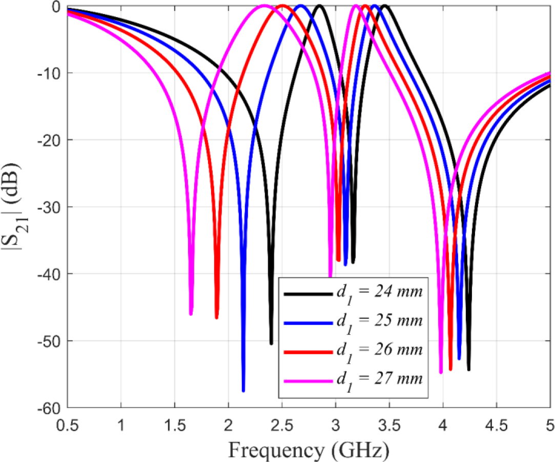
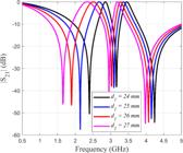
The first parameter analyzed was the length of the outer loop, denoted as d1, which primarily controls the first resonance. In loop-based FSS designs, resonance occurs when the loop’s perimeter is approximately equal to the wavelength at the desired frequency. For a target frequency of 1.56 GHz, the corresponding free-space wavelength is 92 mm, implying that d1 should be close to 23 mm. The initial value was set at 24 mm. Throughout all parametric analyses, the periodicity was fixed at p = 29 mm, and the other dimensions were held constant: w1 = 1 mm, d2 = 20 mm, w2 = 1 mm, d3 = 18 mm, and w3 = 1 mm. The parameter d1 was varied from 24 mm to 27 mm in 1 mm steps. As d1 increases, the outer loops become closer to those of adjacent unit cells, leading to an increase in inter-element capacitance. Simultaneously, the inductance of the loop also increases, causing the first resonant frequency to shift downward. While some influence is also observed on the second and third resonances, the effect is significantly more pronounced for the first band. The resulting transmission coefficient responses are shown in Fig. 3.
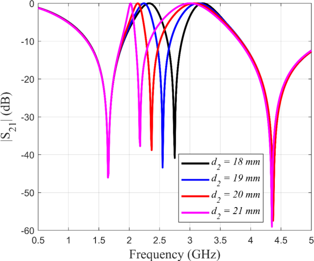
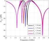
The second parameter analyzed was the length of the middle loop, denoted as d2, which primarily controls the second resonance. At the target frequency of 2.45 GHz, the free-space wavelength is approximately 58 mm, suggesting that d2 should be close to 15 mm. The initial value for the analysis was set at 21 mm. As in previous analyses, the periodicity was fixed at p = 29 mm, and the remaining parameters were held constant: w1 = 1 mm, d1 = 27 mm, w2 = 1 mm, d3 = 18 mm, and w3 = 1 mm. The value of d2 was varied from 21 mm to 24 mm in 1 mm increments. Increasing d2 causes the middle loop to move closer to the outer loop, which leads to an increase in the mutual capacitance between them. In addition, the inductance of the middle loop increases, resulting in a downward shift of the second resonant frequency. The first and third resonances remained largely unaffected by changes in d2. The corresponding transmission coefficient responses are illustrated in Fig. 4.
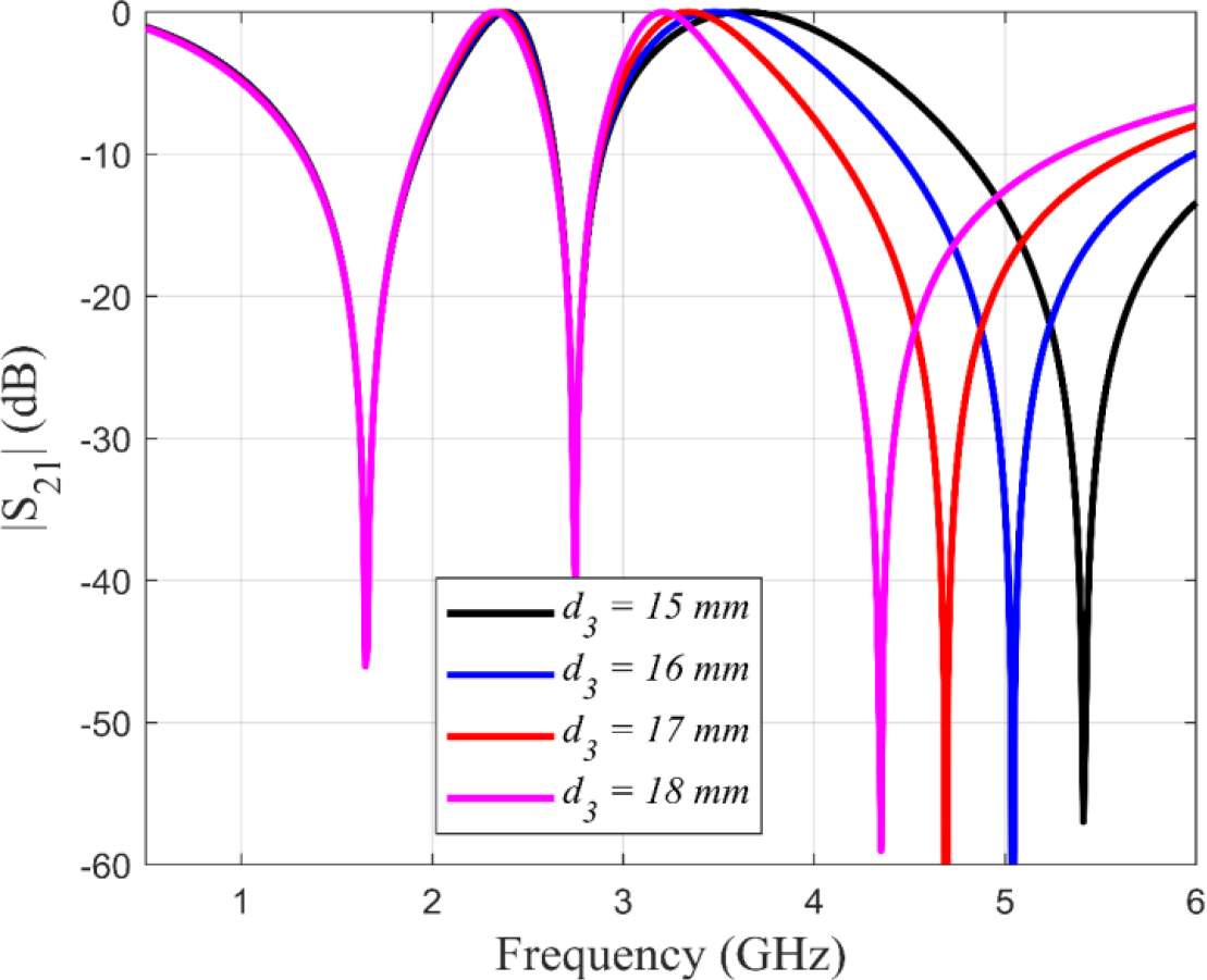
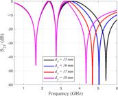
The third parameter analyzed was the length of the innermost loop, denoted as d3, which governs the third resonance. At the target frequency of 3.50 GHz, the corresponding free-space wavelength is approximately 41 mm, indicating that d3 should be near 11 mm. The analysis began with an initial value of 15 mm. As in previous cases, the periodicity was fixed at p = 29 mm, and the other dimensions were held constant: w1 = 1 mm, d1 = 27 mm, w2 = 1 mm, d2 = 21 mm, and w3 = 1 mm. The parameter d3 was varied from 15 mm to 18 mm in 1 mm increments. As d3 increases, the inner loop moves closer to the middle loop, which leads to an increase in mutual capacitance, with a corresponding increase in inductance. These effects cause a downward shift in the third resonant frequency. The first and second resonances remained unaffected by changes in d3. The resulting transmission coefficient responses are shown in Fig. 5.
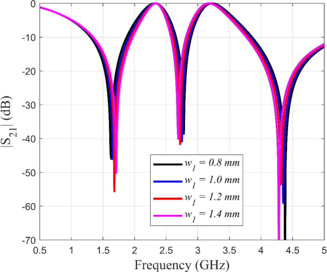
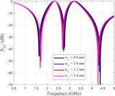
The fourth parameter analyzed was the strip width of the outer loop, denoted as w1. This dimension primarily affects the first resonance by altering the inductance of the largest loop. The analysis was conducted by sweeping the parameter w1 from 0.8 mm to 1.4 mm, within increments of 0.2 mm. As in previous cases, the periodicity was fixed at p = 29 mm, and the other parameters were kept constant: d1 = 27 mm, d2 = 21 mm, w2 = 1 mm, d3 = 18 mm, and w3 = 1 mm. As w1 increases, the inductance of the outer loop decreases slightly, leading to a small upward shift in the first resonant frequency. The second and third resonances also experience minor shifts, though the effects are negligible. The corresponding transmission coefficient responses are presented in Fig. 6.
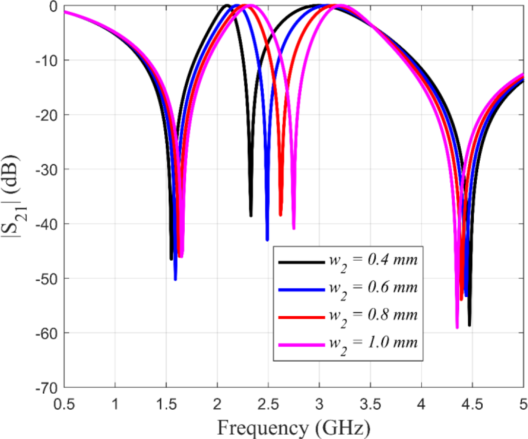
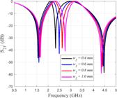
The fifth parameter analyzed was the strip width of the middle loop, denoted as w2. This dimension primarily influences the second resonance by modifying the inductance of the middle loop. The analysis was carried out by changing w2 from 0.4 mm to 1.0 mm, in steps of 0.2 mm. Throughout the analysis, the periodicity was fixed at p = 29 mm, and the remaining parameters were kept constant: d1 = 27 mm, w1 = 1 mm, d2 = 21 mm, d3 = 18 mm, and w3 = 1 mm. As w2 increases, the inductance of the middle loop decreases, resulting in a notable increase in the second resonant frequency. The first and third resonances also experience slight shifts, but their variations are minimal. The corresponding transmission coefficient response is shown in Fig. 7.
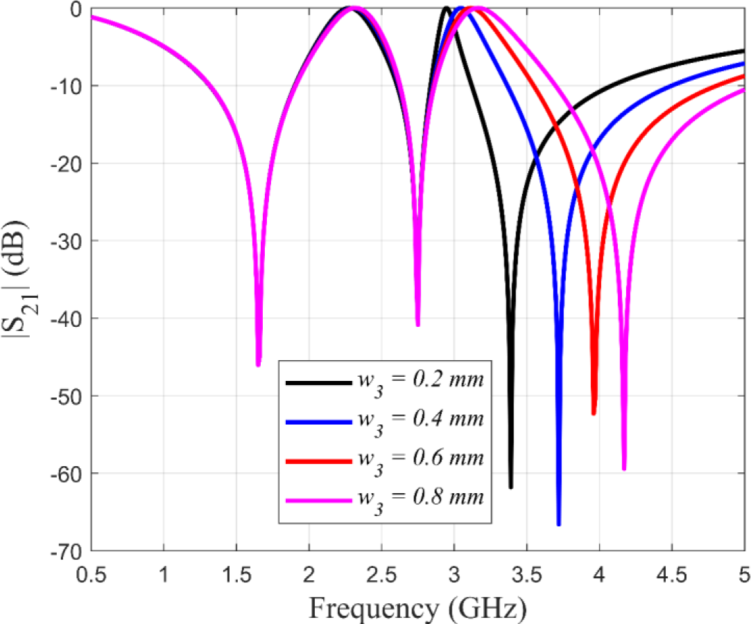
The sixth parameter analyzed was the strip width of the inner loop, denoted as w3. This dimension primarily affects the third resonance by altering the inductance of the inner loop. The parameter w3 was varied from 0.2 mm to 0.8 mm, in steps of 0.2 mm. Throughout this analysis, the periodicity was fixed at p = 29 mm, and the remaining dimensions were kept constant: d1 = 27 mm, w1 = 1 mm, d2 = 21 mm, w2 = 1 mm, and d3 = 18 mm. As w3 increases, the inductance of the inner loop decreases, causing a significant shift in the third resonant frequency. The first and second resonances remained unchanged. The corresponding transmission coefficient response is shown in Fig. 8.
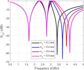
It is important to emphasize that although the variation of wi(i = 1, 2, and 3) is primarily interpreted in terms of inductance reduction, the modification of this parameter also affects the effective capacitance of the structure. Increasing wi not only decreases the self-inductance of the inner loop due to the wider current path but also reduces the effective gap between the inner and middle loops. This reduction enhances the electric field coupling between adjacent conductors, leading to an increase in mutual capacitance. Therefore, the observed shift in the third resonant frequency is not exclusively due to inductance variation, but rather to the combined effect of simultaneous changes in both L and C. As predicted by the resonance condition , the overall frequency behavior results from the balance between the decreasing inductance and the slightly modified capacitance. In the present design, the inductance variation is dominant, which explains the upward frequency shift observed in Fig. 6, 7, and 8, while the capacitance change plays a secondary but non-negligible role in fine-tuning the resonance.
It is well established that analytical L and C expressions derived from Marcuvitz formulations provide accurate results when the unit cell remains electrically small (typically p/λ < 0.3-0.5). In the present work, most analyzed structures exhibit p/λ values between 0.13 and 0.25 at the first resonance, ensuring operation within the quasi-static validity range of the equivalent circuit model. For higher-order resonances where p/λ approaches 0.5-0.6, slightly larger deviations are observed, which is consistent with the known precision limits of analytical ECM formulations reported in the literature. These results confirm that the proposed model operates within its expected reliability domain.
After the parametric analysis, the physical final dimensions of the structure were selected. Table I lists these dimensions.
B. Simulation of the proposed FSS
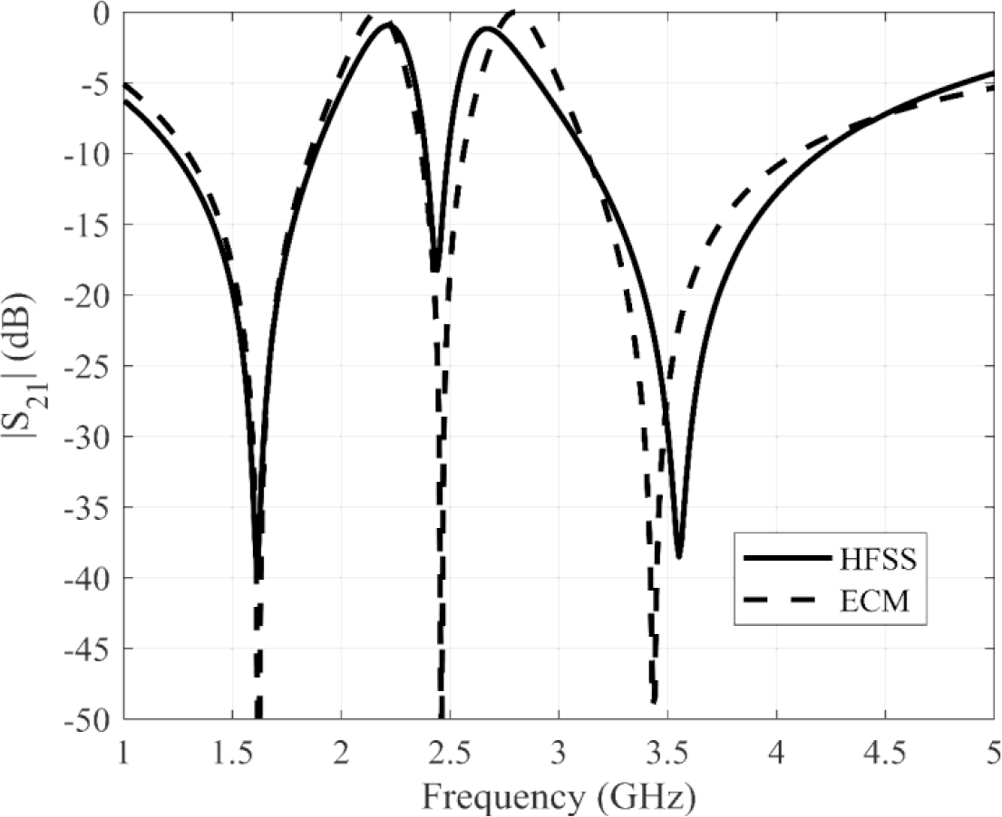
To validate our analysis with the equivalent circuit method, the proposed FSS was simulated in the commercial software HFSS. Fig. 9 illustrates the frequency response of the transmission coefficient of the proposed structure, for normal incidence. The results demonstrate a very good agreement between them. For the results obtained with the ECM, the FSS can reject three frequency bands, with nulls at 1.62 GHz, 2.46 GHz, and 3.43 GHz, with bandwidths of 350 MHz, 190 MHz, and 880 MHz, respectively. The bandwidth is obtained for - 10 dB Transmission level. For the results obtained with HFSS the frequency response shows three nulls at 1.61 GHz, 2.44 GHz, and 3.55 GHz, with bandwidths of 345 MHz, 110 MHz, and 990 MHz, respectively.
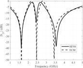
In the full-wave simulations performed in HFSS, the metallic patches were modeled as Perfect Electric Conductors (PEC). Therefore, conductor (ohmic) losses were not included in the numerical analysis. Under this assumption, the insertion losses observed in the simulated results are attributed solely to the dielectric substrate (FR-4), specifically its finite loss tangent, as well as to the intrinsic filtering behavior of the FSS (i.e., power reflection in the stopbands). The PEC approximation was adopted to simplify the model and to emphasize the electromagnetic response governed by the geometry and dielectric properties. It is important to note that, in the fabricated prototype, finite conductivity and surface roughness of the copper layer introduce additional losses, which are naturally included in the experimental results but are not accounted for in the PEC-based simulations.
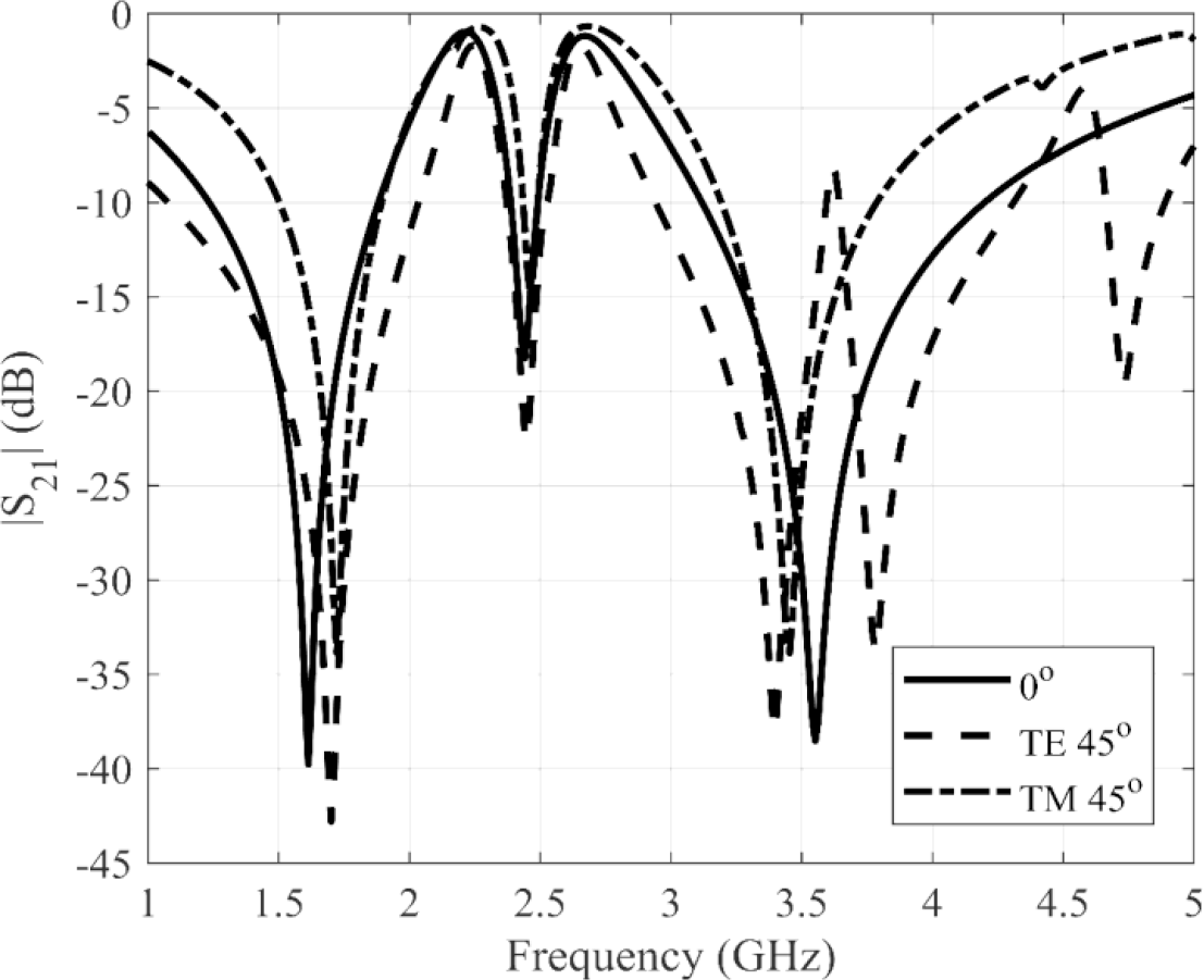
Fig. 10 illustrates the frequency response of the transmission coefficient for oblique incidence, TE and TM modes. The simulated results demonstrate the angular stability of the proposed FSS. To confirm the angular stability, the ratio between the resonance frequency and the ratio between the bandwidth (BW) for normal and oblique incidence at 45° are used. For the resonant frequency of TE mode, the simulated results show that the ratio was 1.05 for the first resonance, 1.00 for the second resonance, and 0.96 for the third resonance. For the BW, the ratios were 0.71, 0.63, and 0.72 for the first, second, and third bands, respectively. For the resonant frequency of TM mode, the simulated results show that the ratio was 0.94 for the first resonance, 0.99 for the second resonance, and 1.03 for the third resonance. For the BW, the ratios were 1.73, 1.67, and 1.98 for the first, second, and third bands, respectively. The frequency response of our proposed structure changes for oblique incidence up to 45°, in terms of bandwidth, but not in terms of resonance frequency, and this change is acceptable.
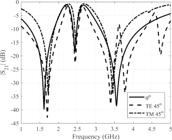
As shown in Fig. 10, while the resonance frequencies remain stable up to 45°, the -10 dB bandwidth exhibits noticeable variation for TM polarization. It is important to emphasize that, for the intended applications (GPS at 1.56 GHz, Wi-Fi at 2.45 GHz, and sub-6 GHz 5G at 3.5 GHz), the bandwidth requirement is guaranteed. For band L1 (1.563 - 1.587 GHz), 24 MHz of band and our FSS provided 400 MHz (1.49 - 1.89 GHz). For Wi-Fi the required band is 83.5 MHz (2.40 - 2.4835 GHz) and the FSS provided 85 MHz (2.40 - 2.485 GHz). Finally, for sub-6 GHz 5G the required band is 500 MHz and the FSS provided 600 MHz band (3.2 - 3.8 GHz). There is preservation of the resonance frequency and the bandwidth for the worst case. So, the structure maintains good angular stability.
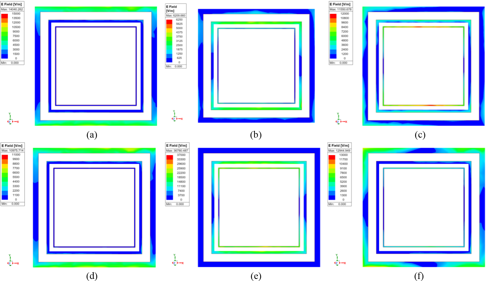
The understanding of the electric field can explain the angular stability. The electric field distributions were also analyzed for the three resonant frequencies, for normal incidence and oblique incidence at 45°, for TE incidence. Fig. 11 (a), 11 (b), and 11 (c) correspond to electric field at 1.62 GHz, 2.44 GHz, and 3.44 GHz, respectively, with normal incidence, while Fig. 11 (d), 11 (e), and 11 (f) show the electric field for oblique incidence of 45° at same frequencies. It is observed in these figures that for 1.62 GHz, the electric field distribution is more intense in the outer loop, for 2.44 GHz the electric field is more intense in the second and third loops, and for 3.44 GHz, the electric field is more intense in the inner loop. Also, the electric field distribution is symmetric, which is a condition for angular stability [35].
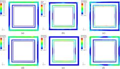
TE Electric field distribution: (a) 1.62 GHz, (b) 2.44 GHz, and (c) 3.44 GHz, and normal incidence, (d) 1.62 GHz, (e) 2.44 GHz, and (f) 3.44 GHz, and oblique incidence at 45°.
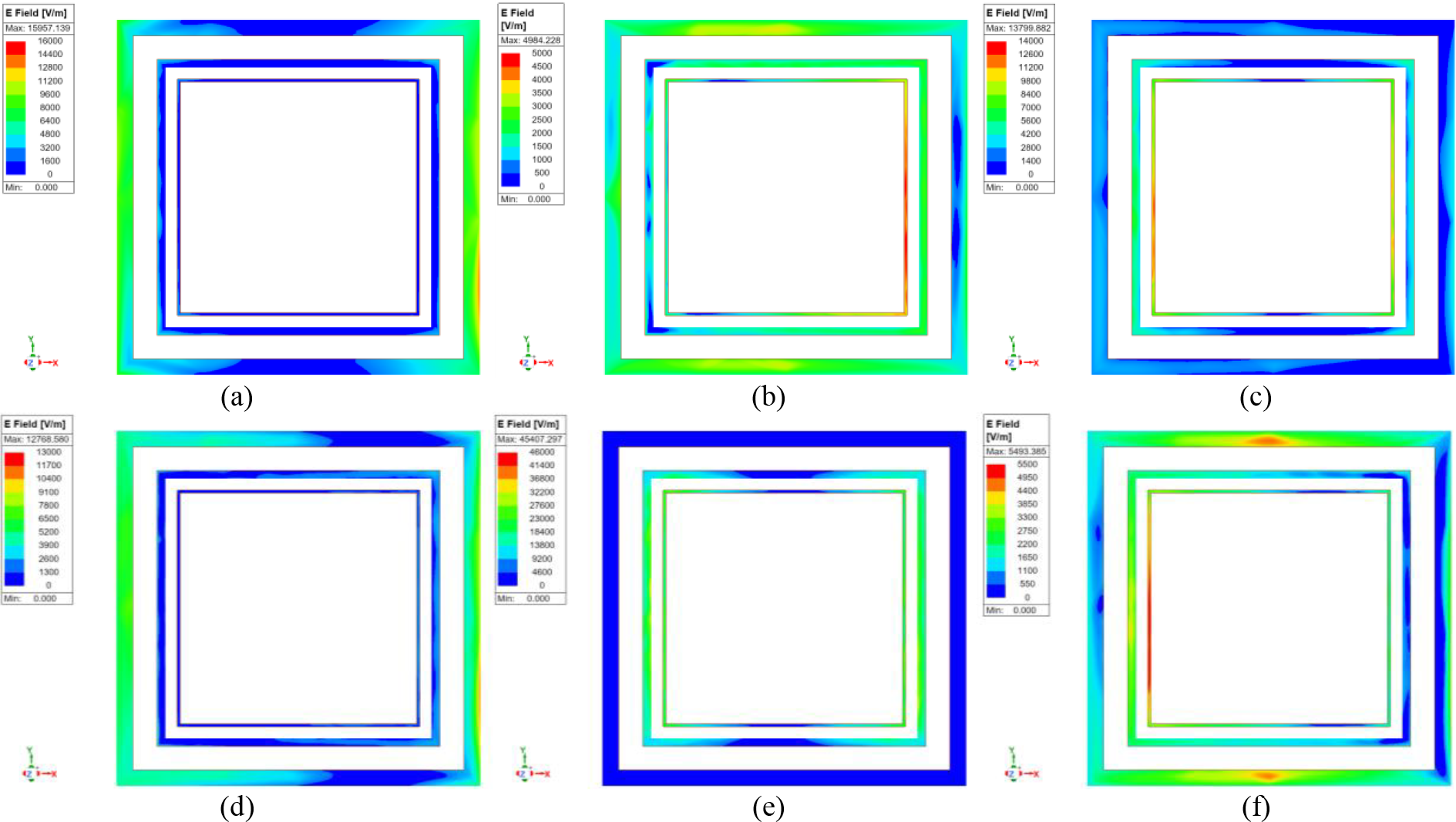
It is important to analyze those fields for the three resonant frequencies, for normal incidence and oblique incidence at 45°, for TM incidence. Fig. 12 (a), 12 (b), and 12 (c) correspond to electric field at 1.62 GHz, 2.44 GHz, and 3.44 GHz, respectively, with normal incidence, while Fig. 12 (d), 12 (e), and 12 (f) show the electric field for oblique incidence of 45° at same frequencies. The figures indicate the same behavior for Fig. 11, with a symmetric electric field distribution.
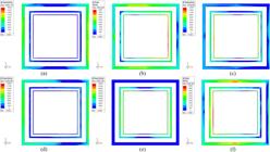
TM Electric field distribution: (a) 1.62 GHz, (b) 2.44 GHz, and (c) 3.44 GHz, and normal incidence, (d) 1.62 GHz, (e) 2.44 GHz, and (f) 3.44 GHz, and oblique Incidence at 45°.
III. EXPERIMENTAL RESULTS
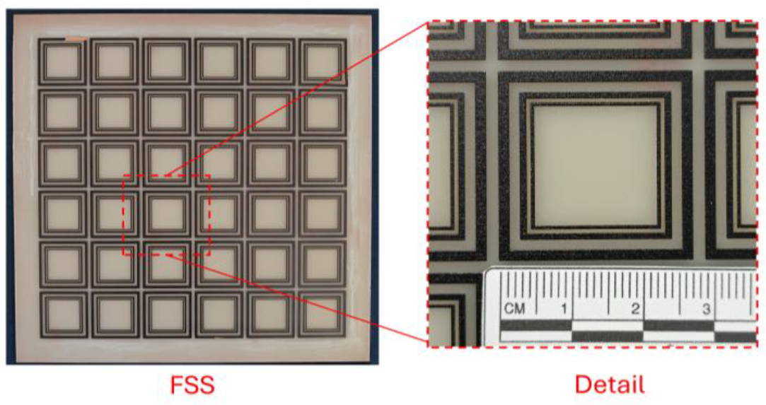
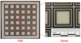
To obtain experimental results and to validate the simulations obtained in this work, we built and measured an FSS prototype with triple loops on a FR-4 substrate of 20×20 cm2, with εr = 4.4 and 1.6 mm thickness. Fig. 13 illustrates the prototype.
A schematic measurement setup is illustrated in Fig. 14 (a). The FSS was fixed on a supporting structure with 79×61 cm2 coated on one side with pyramidal RF absorbers and aluminum foil backing, to avoid diffraction contamination of measurements. The prototype size (20 × 20 cm2) was selected to provide multiple unit cells, reducing truncation effects. Careful alignment was performed to maintain normal incidence conditions. A VNA Rohde & Schwarz ZND 114 is used, and it was calibrated prior to measurements using a full two-port calibration (Short, Open, Load, Through) at the cable ends to remove systematic errors. This ensured that measurements correspond exclusively to the free-space transmission response. For the normal incidence measurement, the transmitter and receiver sides were connected to two identical wide band (700 MHz to 18 GHz) horn antennas. The separation between the transmitting and receiving horn antennas was set to 1.30 m to satisfy far-field conditions. The far-field distance was estimated using R ≥ 2D2/λ where D (250 mm) is the largest dimension of the horn antenna and λ is the wavelength at the lowest operating frequency (≈1.56 GHz). Considering the antenna aperture dimensions and the longest wavelength (≈192 mm in free space), the calculated far-field requirement (0.65 m) is smaller than 1.30 m. Therefore, the chosen distance ensures operation well within the radiating far-field region, minimizing near-field coupling effects. Time-gating was not required because the absorber-treated environment and far-field separation already provided sufficient suppression of multipath reflections within the measurement bandwidth. For oblique incidence measurements, the supporting structure with the FSS can be rotated, as can be seen in Fig. 14 (b).
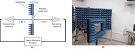
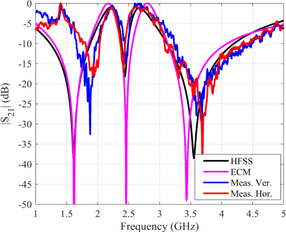
Fig. 15 presents a comparison between the simulated (HFSS and ECM) and measured results under normal incidence. The simulated resonant frequencies were 1.62 GHz, 2.46 GHz, and 3.43 GHz, for the results obtained with the ECM, and for the results obtained with HFSS they were 1.61 GHz, 2.44 GHz, and 3.55 GHz, while the measured resonances occurred at 1.75 GHz, 2.40 GHz, and 3.58 GHz. The bandwidths were 350 MHz, 190 MHz, and 880 MHz, respectively, for the results obtained with ECM. For the results obtained with HFSS the frequency response has bandwidths of 345 MHz, 110 MHz, and 990 MHz, respectively. For measured results the bandwidths were 390 MHz, 90 MHz, and 1120 MHz. The results show good agreement.
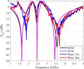
The measured shift of the first and second resonances is mainly attributed to practical factors such as fabrication tolerances, uncertainties in the FR-4 substrate permittivity, finite array effects (since simulations assume infinite periodicity), and minor imperfections in the measurement setup. These combined effects can slightly alter the effective inductance and capacitance of the structure, leading to the observed frequency deviation while preserving the overall triple-band behavior.
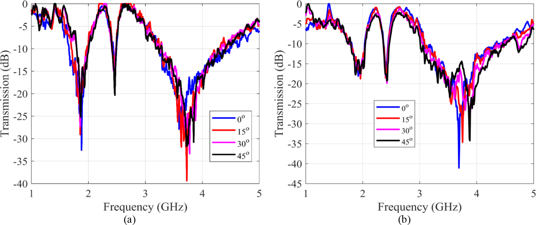
In Fig. 16 (a) the measured results for TE modes are observed, with oblique incidence. The angles of incidence range from 0° to 45°. The analysis reveals three distinct resonance notches across the frequency range, centered approximately at 1.62 GHz, 2.44 GHz, and 3.45 GHz. These notches correspond to the stopbands introduced by the frequency selective surface (FSS). The resonance frequencies remain nearly constant as the angle of incidence increases, indicating minimal angular dispersion. The first resonance shows moderate bandwidth across all angles, with only minor variations in width and depth. The second resonance is relatively narrow at normal incidence but becomes slightly broader and deeper as the angle increases. The third resonance exhibits a more pronounced change in depth and width, especially at 45°, where the notch becomes significantly deeper and slightly wider. The structure demonstrates good angular stability, as the resonant frequencies do not shift significantly up to 45° of incidence. While the depth and bandwidth of the notches are mildly affected, the overall frequency-selective behavior is preserved. This stability implies that the design is robust against incident angle variations.
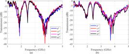
Fig. 16 (b) illustrates measured results for TM modes, with oblique incidence. Again, the angles of incidence range from 0° to 45°. The behavior of the system under varying angles reveals several important features. Three prominent resonance dips are visible, approximately at the same frequencies of that for TE modes. These frequencies show minimal shift with increasing angle, indicating that the structure maintains its frequency-selective behavior even under oblique incidence. The first resonance remains relatively stable in bandwidth across all angles, with only slight variations in depth. The second resonance is sharper at normal incidence and shows mild broadening as the angle increases. The third resonance exhibits a slightly deeper and broader notch at larger angles, but the center frequency remains stable. Overall, bandwidths are preserved reasonably well, with small increases in higher-angle scenarios, especially at higher frequencies. Across all three resonance regions, the structure demonstrates excellent angular stability.
A quantitative evaluation of the simulated and measured insertion losses shows that, from Fig. 15, under normal incidence, the insertion losses for simulations are 0.94 dB and 1.17 dB in the first and second passbands, respectively. For measured results, considering the worst cases, for TE polarization the insertion losses are 1.16 dB and 1.04 dB in the first and second passbands, respectively, while for TM polarization they are 1.06 dB and 1.42 dB. These values confirm that the insertion loss remains around 1 dB in both transmission bands and for both polarizations, demonstrating polarization-independent behavior. The losses are mainly due to the FR-4 dielectric losses and finite copper conductivity. Even with a low-cost substrate, the structure maintains insertion losses below 1.5 dB.
A complementary analysis is done using the angle mean deviation (δfp) that is an important metric to understand the angular independence characteristics of the FSS screens. The angle mean deviation is estimated using (21) as given below [36]:
where and are the central frequencies corresponding to normal and oblique incidences θ, respectively. The calculated angle mean deviation is listed in Table II. The deviation in the central operating frequency is close to 0% for TE and TM modes of operation for values of θ up to 45o. Although the proposed FSS offers good angular independence characteristics, with δfp < 5% for the three frequencies.
The average polarization shift for oblique incidences under both orthogonal polarization modes of operation is estimated using (22) [36]:
where (22), and are the resonant frequencies corresponding to TM and TE modes of operation for various oblique incidence angles θ, and n refers to the number of sample oblique incidences used in the calculation.
The change in the FSS behavior for different polarizations and under different angles of incidence is described in Table III. The calculated shift in the polarization is less than 0.95%. This index proves that the proposed FSS offers excellent polarization stability under oblique incidences.
AVERAGE POLARIZATION SHIFT FOR OBLIQUE INCIDENCES UNDER BOTH ORTHOGONAL POLARIZATION MODES.
Table IV demonstrates the performance comparison of similar existing work with the proposed FSS. This comparison highlights that the proposed design achieves:
-
• A single-layer configuration,
-
• Low cost substrate,
-
• No lumped components or vias,
-
• Stable resonance frequencies up to 45° for both TE and TM polarizations,
-
• Insertion losses close to 1 dB,
-
• Well-defined and adequately spaced operating bands covering GPS (1.56 GHz), Wi-Fi (2.45 GHz), and sub-6 GHz 5G (3.5 GHz).
While some reported designs achieve triple-band performance, they often require multilayer configurations, more complex geometries, or exhibit higher insertion losses and reduced angular stability. The table therefore clarifies that the main contribution of this work lies in achieving competitive electrical performance with reduced structural complexity and low fabrication cost.
IV. CONCLUSIONS
In this work, a novel single-layer triple-band Frequency Selective Surface (FSS) based on triple concentric square loops was proposed. The geometry was selected for its simplicity, low insertion loss, angular stability, and polarization independence. An equivalent circuit model (ECM) was employed to guide parametric analysis, enabling a faster and more intuitive design process without relying exclusively on full-wave simulations. The structure was optimized using HFSS and fabricated on an FR-4 substrate. Experimental results showed good agreement with simulations, confirming the expected resonances at approximately 1.75 GHz, 2.40 GHz, and 3.58 GHz, with suitable bandwidths. Moreover, measurements demonstrated that the resonance frequencies remained nearly unchanged for incidence angles up to 45°. While slight variations in bandwidth and notch depth were observed with increasing angle, the filtering performance was not degraded. These results confirm that the proposed FSS exhibits excellent stability under oblique incidence and insensitivity to polarization, key attributes for practical scenarios involving variable wave incidence. Additionally, the passbands between the stopbands exhibited low insertion loss, outperforming many previously reported designs in the literature. The proposed FSS can be used as a filtering radome or superstrate for sub-6 GHz 5G antennas at 3.5 GHz, providing spectral selectivity with low insertion loss and good angular stability. It may also serve as an electromagnetic shielding surface to improve coexistence between GPS, Wi-Fi, and 5G systems, or be integrated with antennas to enhance out-of-band suppression and EMC performance. Its low-profile, single-layer design and polarization independence make it suitable for practical sub-6 GHz 5G applications.
ACKNOWLEDGMENT
The authors are thankful towards Coordination of Superior Level Staff Improvement for fellowship and National Council for Scientific and Technological Development, under the grant 304099/2024-4.
DATA AVAILABILITY
The data that support the findings of this study are available from the corresponding author, Nickson S. O. L., upon reasonable request.
REFERENCES
-
[1] K. Wu, W. Xu, P. Li, J. Zhou and W. Li, "Miniaturized element frequency selective surface design for high power microwave applications", The Institution of Engineering and Technology - Microwave, Antennas & Propagation, vol. 17, no. 11, pp. 846-856, 2023. doi: 10.1049/mia2.12401
» https://doi.org/10.1049/mia2.12401 -
[2] T. S. Evangelista, J. S. Souza, A. J. R. Serres and A. G. Neto, "Frequency selective surfaces as reconfigurable superstrate applied to a dipole antenna for 5G NR", Journal of Microwave, Optoelectronics and Electromagnetic Applications, vol. 23, pp. e2024281340:1-e2024281340:15, 2024. doi: 10.1590/2179-10742024v23i2281340
» https://doi.org/10.1590/2179-10742024v23i2281340 -
[3] Y. Cao, J. Zhang, C. Tian, Y. Liu, J. Zhang and W. Zhang, "Design of a frequency selective surface-backed microstrip reflectarray antenna using Minkowski ring elements", International Journal of Radio Frequency and Microwave Computer-Aided Engineering, vol. 32, pp. e23136:1-e23136:12, 2022. doi: 10.1002/mmce.23136
» https://doi.org/10.1002/mmce.23136 -
[4] S. H. Kiani, U. Rafique, H. Ş. Savci, H. Rmili, N. O. Parchin, A. D. Algarni and H. Elmannai, "Performance enhancement of Vivaldi-shaped planar UWB antenna using a single-layer FSS reflector", AEU - International Journal of Electronics and Communications, vol. 178, pp. 155302:1-155302:11, 2024. doi: 10.1016/j.aeue.2024.155302
» https://doi.org/10.1016/j.aeue.2024.155302 -
[5] Y. Amraoui, I. Halkhams, R. El Alami, MO. Jamil and H. Qjidaa, “Terahertz dual-band antenna design with improved performances using FSS-based metasurface concept for wireless applications”, Scientific African, vol. 27, pp. e02566:1-e02566:11, 2025. doi: 10.1016/j.sciaf.2025.e02566
» https://doi.org/10.1016/j.sciaf.2025.e02566 -
[6] L. Wei, C. Ma, X. Liu, H. Ma, Y. Wu, Z. Fan and J. Huangfu, "Dual-band and dual-polarized reflective Fresnel zone plate design based on Fractal shape", Scientific Reports, vol. 13, pp. 6222:1-6222:11, 2022. doi: 10.1038/s41598-023-33446-y
» https://doi.org/10.1038/s41598-023-33446-y -
[7] M. Tang, Q. Liu, D. Zhou, Q. Liu, Z. Yao and C Pan, "Miniaturised frequency selective surface-based rasorber with wideband two-sided absorption and switchable transmission/reflection band", The Institution of Engineering and Technology - Microwave, Antennas & Propagation, vol. 17, no. 4, pp. 284-291, 2023. doi: 10.1049/mia2.12337
» https://doi.org/10.1049/mia2.12337 -
[8] MI. Hossain, N. Nguyen-Trong and AM. Abbosh, "Broadband magnetic absorber based on double-layer frequency-selective surface", IEEE Transactions on Antennas and Propagation, vol. 70, no. 1, p. 410-419, 2022. doi: 10.1109/TAP.2021.3096199
» https://doi.org/10.1109/TAP.2021.3096199 -
[9] J. Kim, H. -K. Jang, J. Oh and J. Park, "A rational design procedure for absorbers of square-loop-shaped resistive frequency selective surface placed on glass/epoxy laminate", IEEE Transactions Electromagnetic Compatibility, vol. 65, no. 1, pp. 104-113, 2023. doi: 10.1109/temc.2022.3219378
» https://doi.org/10.1109/temc.2022.3219378 -
[10] X. Li. et al., "Preparation, microstructure and performance of interference microwave absorbing cermet composites with frequency-selective screens", Ceramics International, vol. 48, no. 23, pp. 34199-34209, 2022. doi: 10.1016/j.ceramint.2022.04.313
» https://doi.org/10.1016/j.ceramint.2022.04.313 -
[11] X. Li, L. Zhu, D. Sun, Q. Yang, Y. Liu, W. Yu and CC. Lv, "A new miniaturized active frequency selective surface with convoluted element for UHF applications", Journal of Microwave, Optoelectronics and Electromagnetic Applications, vol. 23, no. 1, pp. e2024278519:1- e2024278519:9, 2024. doi: 10.1590/2179-10742024v23i1278519
» https://doi.org/10.1590/2179-10742024v23i1278519 -
[12] J. Singh, AS. Jain, N. Narang and D. Singh, "An efficient application of machine learning for designing user specific transmissive radome", Microwave and Optical Technology Letters, vol. 65, no. 7, pp. 1873-1879, 2023. doi: 10.1002/mop.33646
» https://doi.org/10.1002/mop.33646 -
[13] F. Guan, D. Li, J. Li, Z. Yang, Y. Lei, Z. You, Z. Li and Y. Tao, "Analysis of electromagnetic transmission characteristics of square loop frequency selective fabrics with different layers", Textile Research Journal, vol. 92, no. 21-22, pp. 4288-4297, 2022. doi: 10.1177/00405175221101178
» https://doi.org/10.1177/00405175221101178 -
[14] I. S. Silva Junior, A. Gomes Neto, M. W. B. Silva, A. L. P. S. Campos, "Dual-band monopole antenna integrated with frequency selective surface for possible use in non-invasive biomedical applications", Journal of Microwave, Optoelectronics and Electromagnetic Applications, vol. 23, pp. e2024282634:1-e2024282634:19, 2024. doi: 10.1590/2179-10742024v23i3282634
» https://doi.org/10.1590/2179-10742024v23i3282634 -
[15] A. Varshney and D. N. Gençoğlan, "High-gain multi-band koch fractal FSS antenna for sub-6 GHz applications", Applied Sciences, vol. 14, no. 19, pp. 9022:1-9022:26, 2024. doi: 10.3390/app14199022
» https://doi.org/10.3390/app14199022 -
[16] X. F. Wang, Y. Li, L. L. Yang, W. W. Yang and J. X. Chen, "Mesh-based antenna with broadband transparency for dual-band shared-aperture array", AEU - International Journal of Electronics and Communications, vol. 178, pp. 155286:1-155286:9, 2024. doi: 10.1016/j.aeue.2024.155286
» https://doi.org/10.1016/j.aeue.2024.155286 -
[17] M. L. Hakim, M. T. Islam and T. Alam, "Incident angle stable broadband conformal mm-Wave FSS for 5G (n257, n258, n260, and n261) band EMI shielding application", IEEE Antennas and Wireless Propagation Letters, vol. 23, no. 2, pp. 488-492, 2024. doi: 10.1109/LAWP.2023.3326868
» https://doi.org/10.1109/LAWP.2023.3326868 -
[18] Srimita Coomar, Rajarshi Sanyal, and Santanu Mondal, "Metamaterial inspired UltraThin polarization-separated UWB FSS to mitigate Ku and K-Band electromagnetic interference", AEU - International Journal of Electronics and Communications, vol. 194, pp. 155764:1-155764:16, 2025. doi: 10.1016/j.aeue.2025.155764
» https://doi.org/10.1016/j.aeue.2025.155764 -
[19] P. Njogu, B. Sanz-Izquierdo, Z. Chen and E. A. Parker, "Three-dimensional frequency selective surface displacement sensor using complementary dielectrics", IEEE Sensors Journal, vol. 23, no. 16, pp. 18692-18699, 2023. doi: 10.1109/JSEN.2023.3289777
» https://doi.org/10.1109/JSEN.2023.3289777 -
[20] M. L. Neyestanak, H. Moghadas, S. Mirabbasi and P. Servati, "Compact fractal-shaped frequency selective surface for distant liquid sensing with multiple sensitive spots", IEEE Sensors Journal, vol. 25, no. 9, pp. 15031-15042, 2025. doi: 10.1109/JSEN.2025.3547410
» https://doi.org/10.1109/JSEN.2025.3547410 -
[21] S. Chen, C. F. Fan, J. T. Sun, Y. Liu, X. H. Hu, J. Liu, Q. Liu and K. Gong, "A tri-band frequency selective surface with angular stability based on hexagonal structure", IEEE 12th Asia-Pacific Conference on Antennas and Propagation (APCAP), pp. 1-2, 2024. doi: 10.1109/APCAP62011.2024.10881548
» https://doi.org/10.1109/APCAP62011.2024.10881548 -
[22] C. N. E. Dhanesh, M. Janani, A. Sasmitha and S. Ramprabhu, "Design of textile based tri-band FSS for 5G mmWave shielding", International Conference on Wireless Communications Signal Processing and Networking (WiSPNET), pp. 1-4, 2024. doi: 10.1109/WiSPNET61464.2024.10532800
» https://doi.org/10.1109/WiSPNET61464.2024.10532800 -
[23] K. Katoch, N. Jaglan, B. K. Kanaujia, P. Y. Chen and A. A. Kishk, "Triple bandstop 2.5D frequency selective surface for sub-6 GHz 5G communication", IEEE Transactions on Electromagnetic Compatibility, vol. 66, no. 5, pp. 1420-1429, 2024. doi: 10.1109/TEMC.2024.3445292
» https://doi.org/10.1109/TEMC.2024.3445292 -
[24] Z. Li, X. Weng, X. Yi, K. Li, W. Duan and M. Bi, "Design and analysis of a complementary structure-based high selectivity tri-band frequency selective surface", Scientific Reports, vol. 14, no. 1, pp. 9415:1-9415:10, 2024. doi: 10.1038/s41598-024-59712-1
» https://doi.org/10.1038/s41598-024-59712-1 -
[25] D. J. Yun, Y. P. Hong, I. H. Lee, M. S. Kim, J. C. Lee and I. J. Hwang, "A multifunctional frequency selective surface with a wide incident angle for X-/K-/Ka-band applications", IEEE Antennas and Wireless Propagation Letters, vol. 23, no. 11, pp. 3574-3578, 2024. doi: 10.1109/LAWP.2024.3411053
» https://doi.org/10.1109/LAWP.2024.3411053 -
[26] M. Sainath, M. G. Reddy and S. S. Karthikeyan, "Compact wideband FSS bandstop filter for S, C, and X band applications", Journal of Applied Physics, vol. 137, no. 17, pp. 173102:1-173102:10, 2025. doi: 10.1063/5.0257092
» https://doi.org/10.1063/5.0257092 -
[27] M. Sainath and N. C. Pradhan, "Design and Manufacturing of an All-Metal Triple-Bandpass Frequency-Selective Surface Filter Using Laser Cutting Technology", IEEE Transactions on Components, Packaging and Manufacturing Technology, vol. 15, no. 3, pp. 463-469, 2025. doi: 10.1109/TCPMT.2025.3539303
» https://doi.org/10.1109/TCPMT.2025.3539303 -
[28] S. Subbaraj, S. Ramadoss and S. K. Palaniswamy, "A novel miniaturized single-layer frequency selective surface with triband characteristics", International Journal of Antennas and Propagation, vol. 2025, no. 1, pp. 4053255:1-4053255:8, 2025. doi: 10.1155/ijap/4053255
» https://doi.org/10.1155/ijap/4053255 -
[29] B. S. da Silva, A. L. P. S. Campos, M. E. T. Sousa, A. G. Neto, H. D. de Andrade, “A tri-band complementary frequency selective surface with very closely spaced resonances”, The Institution of Engineering and Technology - Microwave, Antennas & Propagation, vol. 16, no. 18, pp. 519-525, 2022. doi: 10.1049/mia2.12262
» https://doi.org/10.1049/mia2.12262 -
[30] Hocine M. and Mouffok L., “Analytical modeling of a triple-band artificial magnetic conductor”, TechRxiv, pp. 1-3, 2024. doi: 10.36227/techrxiv.170956729.92594453/v1
» https://doi.org/10.36227/techrxiv.170956729.92594453/v1 -
[31] R. J. Langley and E. A. Parker, “Equivalent circuit model for arrays of square loops”, Electronics Letters, vol. 18, no. 7, pp. 294-296, 1982. doi: 10.1049/el:19820201
» https://doi.org/10.1049/el:19820201 -
[32] R. J. Langley and E. A. Parker, “Double-square frequency-selective surfaces and their equivalent circuit”, Electronics Letters, vol. 19, no. 15, pp. 675-677, 1983. doi: 10.1049/el:19830460
» https://doi.org/10.1049/el:19830460 - [33] N. Marcuvitz, “Waveguide Handbook”, The Institution of Engineering and Technology, vol. 10, pp. 1-428, 1951.
-
[34] F. Costa, A. Monorchio and G. Manara, “Efficient analysis of frequency-selective surfaces by a simple equivalent-circuit model”, IEEE Antennas and Propagation Magazine, vol. 54, no. 4, pp. 36-48, 2012. doi: 10.1109/MAP.2012.6309153
» https://doi.org/10.1109/MAP.2012.6309153 -
[35] B. Lin, J. Wu, X. Da, W. Li and J. Ma, “A linear-to-circular polarization converter based on a second-order band-pass frequency selective surface”, Applied Physics A, vol. 123, no. 43, pp. 43:1-43:5, 2017. doi: 10.1007/s00339-016-0673-8
» https://doi.org/10.1007/s00339-016-0673-8 -
[36] S. Andi and Ramesh G. P., “Miniaturized frequency-selective surface with reduced number of metallic vias for electromagnetic shielding”, International Journal Communication Systems, vol. 36, nº 17, pp. e5599:1- e5599:10, 2023. doi:10.1002/dac.5599
» https://doi.org/10.1002/dac.5599
-
Editor:
Carlos E. Capovilla
-
Associate Editor:
Rafael A. Penchel