 The combination of acidizing and hydraulic fracturing for the stimulation of a tight gas reservoir in Minas Gerais
Abstract
The combination of acidizing and hydraulic fracturing, or proppant-acid fracturing, seems to be a very logical approach to achieve the maximum stimulated volume in tight gas reservoirs, since the acid solution can stimulate the deep microfracture network far beyond the main propped fracture. However, this hybrid stimulation method sparks concerns that acidizing can increase proppant embedment and decrease the propped fracture conductivity. To understand how acidizing may be responsible for reducing conductivity, this article initially delves into the analysis of microscopic images of carbonate and siltstone specimens associated with a low permeability or tight gas reservoir in the São Francisco basin, in Minas Gerais, a kind of reservoir which is becoming considerably more important in recent years due to energy transition initiatives. The microscopic analysis revealed that thin, well-defined layers emerged on the acidized surface of some of the studied specimens. Then additional nanoindentation and proppant embedment tests showed that these new layers are weaker compared to the original rock matrix and are ultimately responsible for fracture conductivity decline. The findings in this study serve as an important piece of information for reservoir stimulation professionals that may consider the combination of acid stimulation and hydraulic fracturing in tight gas formations.
Keywords:
proppant-acid fracturing; proppant embedment; tight gas; fracture conductivity; energy transition
1. Introduction
The idea of proppant-acid fracturing was patented in the last century by Cardwell et al. (1957), but the first of this hybrid stimulation technique has only been published in the last decade (Azevedo et al., 2010; Smith et al., 2018; Che et al., 2018). Likewise, only recently, laboratory studies on proppant-acid fracturing have begun to appear in the scientific literature, highlighting here Zhang et al. (2018), Guo et al. (2019) and Chen et al. (2023).
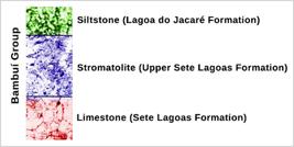
The new laboratory study presented here is based on the comparison of mechanical properties between acidized and non-acidized specimens of carbonate and siltstone rocks. The rocks used in this study are associated with a low permeability reservoir containing dry natural gas from the Bambuí Group in the São Francisco Basin, in Minas Gerais. In the Bambuí Group (Figure 1), the siltstone from Lagoa do Jacaré formation and the carbonates from Sete Lagoas formation are considered the gas-generating rocks; the carbonates from the upper part of the Sete Lagoas Formation, represented by the biogenic carbonates known as stromatolites (Vieira et al., 2007), are the reservoir rocks of the Bambuí Group (Avila et al., 2020).
In the first phase of the study, microscopic analysis of the acidized surfaces revealed thin, well-defined layers resulting from acid attack. The stromatolite, the only rock in this study with a biogenic origin, did not produce new layers due to acid etching and the probable reasons are discussed later herein.
In the second phase of the study, the nanoindentation tests allowed to compare the rock mechanical properties of acidized and non-acidized specimens, followed by proppant embedment tests that allowed to evaluate the fracture conductivity decline in the acidized specimens.
Proppant embedment represents the main cause of fracture conductivity loss (Gao et al., 2013) and the factors that have the greatest influence on proppant embedment are related to the characteristics of the formation (clay content, organic carbon content, porosity of formation, carbonate and quartz content) and the characteristic of the proppant (proppant type, size, and concentration) (Bandara et al., 2019).
All the tests reported here were performed under ambient pressure and temperature conditions. It is assumed, however, that the results of this work, which are based on the reaction rate of hydrochloric acid (HCl) and calcium carbonate (CaCO3), would still be valid for reservoir conditions where pressures and temperatures are generally higher. The reason for this assumption is the fact that temperature and pressure have opposite effects on the reaction rate of HCl and CaCO3. While the effect of increasing temperature is to increase the reaction rate (Alkattan et al., 1998), the effect of increasing pressure is to decrease it, even when gas bubbles resulting from the reaction between HCl and CaCO3 are kept in solution (Mumallah, 1991).
2. Theory
2.1 Fracture conductivity
Fracture conductivity depends on the permeability of the proppant filling the interior of the fracture, and the width of the fracture according to Equation (1):
in the equation above, Fc is the fracture conductivity, kf is fracture permeability, or the proppant permeability, and wf is the fracture width.
The permeability of the proppant can be measured experimentally, or it can be calculated from the empirical Carman-Kozeny equation, Equation(2), widely used to predict the permeability of random sphere packages (Sanematsu et al., 2015).
where dp is the median proppant diameter and φ is the porosity of the proppant package.
2.2 Nanoindentation
The theoretical basis of nanoindentation was stablished by Oliver and Pharr (1992), and generally this process can be carried out either on a constant loading rate (CLR) mode or on a constant strain rate (CSR) mode. The majority of nanoindentation studies in rocks are performed using the CLR mode, where the maximum load needs to be pre-determined and deeper indentation depths indicate inferior mechanical properties (Shi et al., 2020).
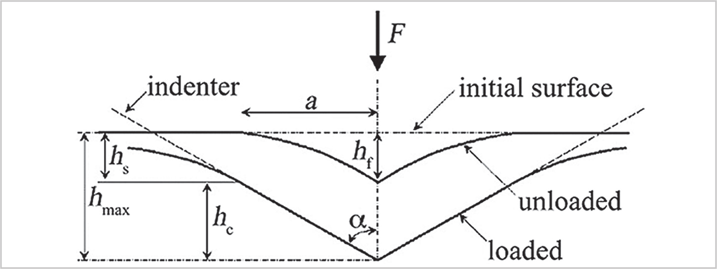
Figure 2 illustrates the nanoindentation process where the indentation depth (ℎmax) in Equation (3) corresponds to the vertical surface deflection at the perimeter of contact (ℎs) plus the contact depth (ℎc).
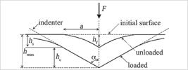
Schematic cross-section of a nanoindentation process. Modified from Oliver and Pharr (1992).
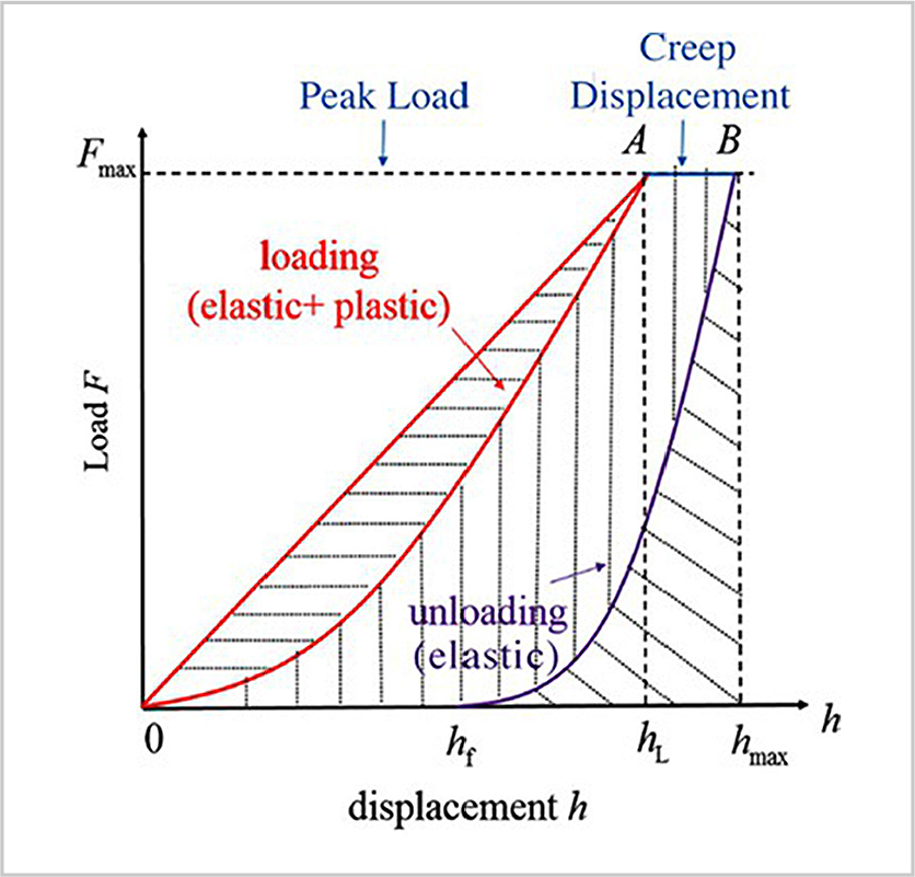
Figure 3 illustrates the load vs. displacement curve which consists of three stages: loading, holding, and unloading.
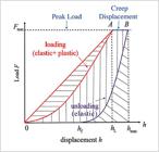
The loading stage is a combination of elastic and plastic deformation, while the unloading stage consists of elastic (recovered) deformation.
The holding stage, also called creep displacement (Li et al., 2019), is used to study creep behavior. According to Liu et al. (2018), as the creep time increases, Young’s modulus and hardness decreases indicating that the sample´s surface becomes softer.
The unloading stage is used to calculate hardness (H) in Equation (4):
Fmax is the peak load and Ac is the projected contact area of the indenter computed by Equation (5):
ℎc is the contact depth defined by Equation (6):
ℎmax is the maximum indentation depth and S is the contact stiffness shown in Equation (7), calculated by the slope of the linear portion of the unloading curve (ℎmax):
where F is the load.
The reduced Young’s modulus (Er) can be calculated from Equation (8):
β is a constant dependent on the geometry of the indenter (1.034 for a Berkovich indenter).
The Young´s modulus (E) can be calculated from Equation (9):
Ei is the Young’s modulus and vi is the Poisson’s ratio of the diamond indenter (for a Berkovith indenter, Ei = 1141 GPa and vi = 0.07), and v is the Poisson’s ratio of the sample, usually taken from literature.
3. Methods and materials
3.1 X-ray fluorescence, x-ray diffraction and carbon phase analysis
X-ray fluorescence (XRF) was used for semi-quantitative chemical analysis while X-ray diffraction (XRD) was used for mineralogical composition analysis of the rock types in Figure 1. Carbon phases, i.e., organic, elemental carbon, and carbonate carbon, were determined by infrared absorption using a LECO carbon analyzer.
3.2 Preparation of samples for optical microscopy, scanning electron microscopy (SEM), and nanoindentation analysis
Sections for microscopy and nano indentation analysis were prepared from 56 mm diameter core samples containing a 6 mm diameter central hole.
During the acidizing procedure, the core samples were positioned vertically and 15% (w/w) HCl was injected in the central hole from the bottom, at a 15 mL/min rate, atmospheric pressure, and laboratory temperature (22o C), for 1 hour. In this dynamic test, the CO2 bubbles continuously moved away from the walls in the central hole, not preventing the contact of the acid with the rock surface.
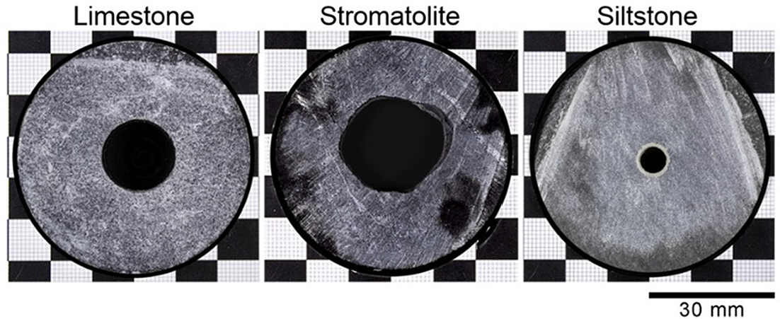
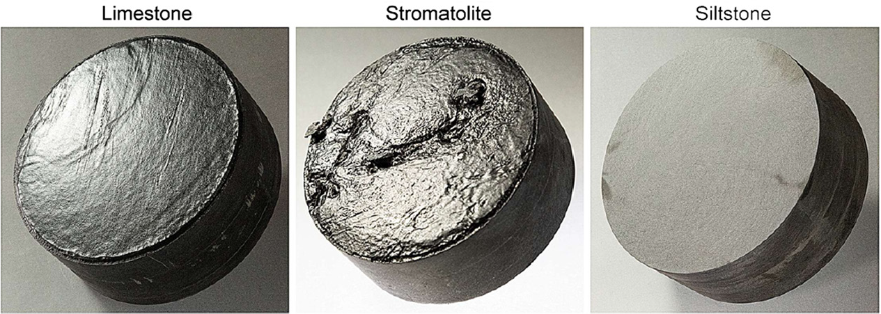
The cross-sections shown in Figure 4 were cut at a distance of 10 mm from the acid entry point. They show the results of acid dissolution in the central hole for the three different types of rocks. The reaction of carbonates (limestone & stromatolite) with HCl (CaCO3 + HCl → CaCl2 + CO2 + H2O) showed the highest dissolution rates, especially in the stromatolite with a rock matrix rich in micropores (Figure 7), effectively exposing more of the rock surface to the acid. The siltstone on the other hand, rich in silicates that do not react with HCl (Figure 8), showed only a bleached layer around the central hole, without any visible enlargement of the original diameter.
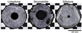
Cross-sections of core samples after injection of 15% hydrochloric acid (HCl) into the 6 mm diameter central hole. Note the difference in reaction rate between the carbonate samples (limestone and stromatolite) and the siltstone.
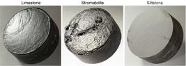
Acidized core samples prepared for proppant embedment tests. Note the different textures between the stromatolite with the highest dissolution rate, and the siltstone with the lowest dissolution rate.
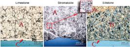
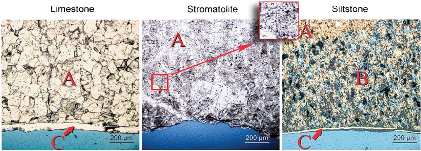
Petrographic thin sections showing the original rock matrix (A) and the neo layers resulting from acid etching (B and C).
After acid etching, the samples in Figure 4 were impregnated with a low-viscosity epoxy resin introduced while the samples were under a vacuum. After the vacuum impregnation, pressure via an inert gas was applied to force the epoxy into small pores. Blue is usually the color chosen to stain the resin, to facilitate the observation of pores under the optical microscope.
3.3 Sample preparation for proppant embedment tests
The specimens for the proppant embedment tests were prepared from larger core samples with 98 mm in diameter and 40 mm in height. Part of the specimens had one of the surfaces acidized by immersion in 300 ml of 15% HCl solution for a period of 1 hour (Figure 5).
4. Results and discussion
4.1. XRF, XRD and carbon phase analysis
The chemical, mineralogical and carbon phase analysis for the rocks associated with the tight gas reservoir are presented in Tables 1, 2 and 3 respectively.
Among the minerals in Table 2, only calcite has a strong reaction with HCl. Between the clay minerals, muscovite and chamosite, the chamosite is more soluble in HCl and it can effectively be dissolved in HCl solutions with a concentration > 1N (3.64 % HCl) (Hu et al., 2022). The quartz and albite (feldspar) are essentially insoluble in HCl.
In Table 3, it can be seen that the stromatolite has a higher content of elemental carbon compared to the limestone. Even though these concentrations apparently are very small, they could theoretically influence the deposition of a calcite layer as further explained in section 4.3.
4.2 Optical Microscopy
Figure 6 shows optical microphotographs of thin sections (0.03 mm) extracted from the surface of the cross-sections in Figure 4. The blue resin that was applied to protect the internal walls of the acidized holes is clearly visible at the bottom of the pictures. The original rock matrix is labeled A, while the new layers resulting from acid etching are labeled B and C. Note the absence of neo layers in the stromatolite, and the blue resin penetrating the voids created by the acid reaction with calcite in the acid invasion zone in the siltstone.
4.3 SEM images
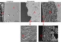
Figure 7 shows SEM images from the surface of the cross-sections in Figure 4. The blue resin applied in the central holes appears dark on the left side of each picture. SEMs achieve higher resolution revealing finer details when compared to optical microscopes, because they rely on a focused beam of electrons that interacts with the sample and have a much shorter wavelength than visible light.
With SEM it is possible to clearly see the crystals forming neo layer C, in the limestone and in the siltstone, and the micropores in the matrix of the stromatolite.
4.4 SEM-energy dispersive X-Ray spectroscopy (EDS)
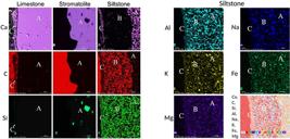
The energy dispersive spectrum (EDS) detector of the SEM provided a chemical mapping of the cross-sections in Figure 7. It is possible to observe in Figure 8 that calcite, indicated by the chemical element Ca, is the only mineral present in neo layer C in the limestone; but in the siltstone, in neo layer C, calcite is together with muscovite (K), albite (Na), chamosite (Fe) and quartz (Si). It seems that the fine grains of muscovite, albite, chamosite, and quartz, that were held together by calcite in the matrix of the siltstone, got lose during the solubilization of calcite in the acid invasion zone B and were cemented together in zone C during the recrystallization process of calcite, at the end of the acidizing procedure. In summary, these observations indicate that the outer neo layer C is the result of the recrystallization of calcite, both in the limestone and in the siltstone.
In Zone B, the acid invasion zone in the siltstone, calcite (Ca) was completely removed, while the other minerals from the matrix A remained intact; there is no observable transition for the chemical elements Si, Al, Na, K, Fe and Mg, from zone B to A, indicating that quartz, muscovite, albite and even chamosite were not removed from the original rock matrix. In summary, zone B is a residual neo layer resulting from the solubilization of calcite alone.
The reason for the absence of a recrystallization neo layer (C) in the stromatolite, whose presence would be expected based on a mineralogical composition similar to the limestone, is probably twofold. Primarily the high dissolution rate observed in the stromatolite creates a turbulent solid-liquid interface, disturbing the fixation of recrystallized calcite at the top of the matrix A. Then, along with the turbulent interface, comes the higher elemental carbon content of the stromatolite (Table 3). Carbon nano particles are efficient calcium carbonate scale inhibitors at concentrations as low as 10 mg/L in aqueous solutions. They change the crystal form of the precipitated calcite, making its adherence to surfaces a difficult task. However, any concentration values below the 10 mg/L threshold sharply reduce the efficiency of carbon as calcite scale inhibitors. (Wan et al., 2019). Therefore, small variations in the low carbon concentration range could have a significant influence on the presence of a calcite deposition neo layer.
4.5 Nanoindentation tests
Nanoindentation tests were carried out using a Berkovich indenter at a constant loading rate of 70 μN/s and a maximum load of 700 μN maintained at peak load for 10 s. The indentation points were located at the vertices of a 50 x 50 μm square grid.
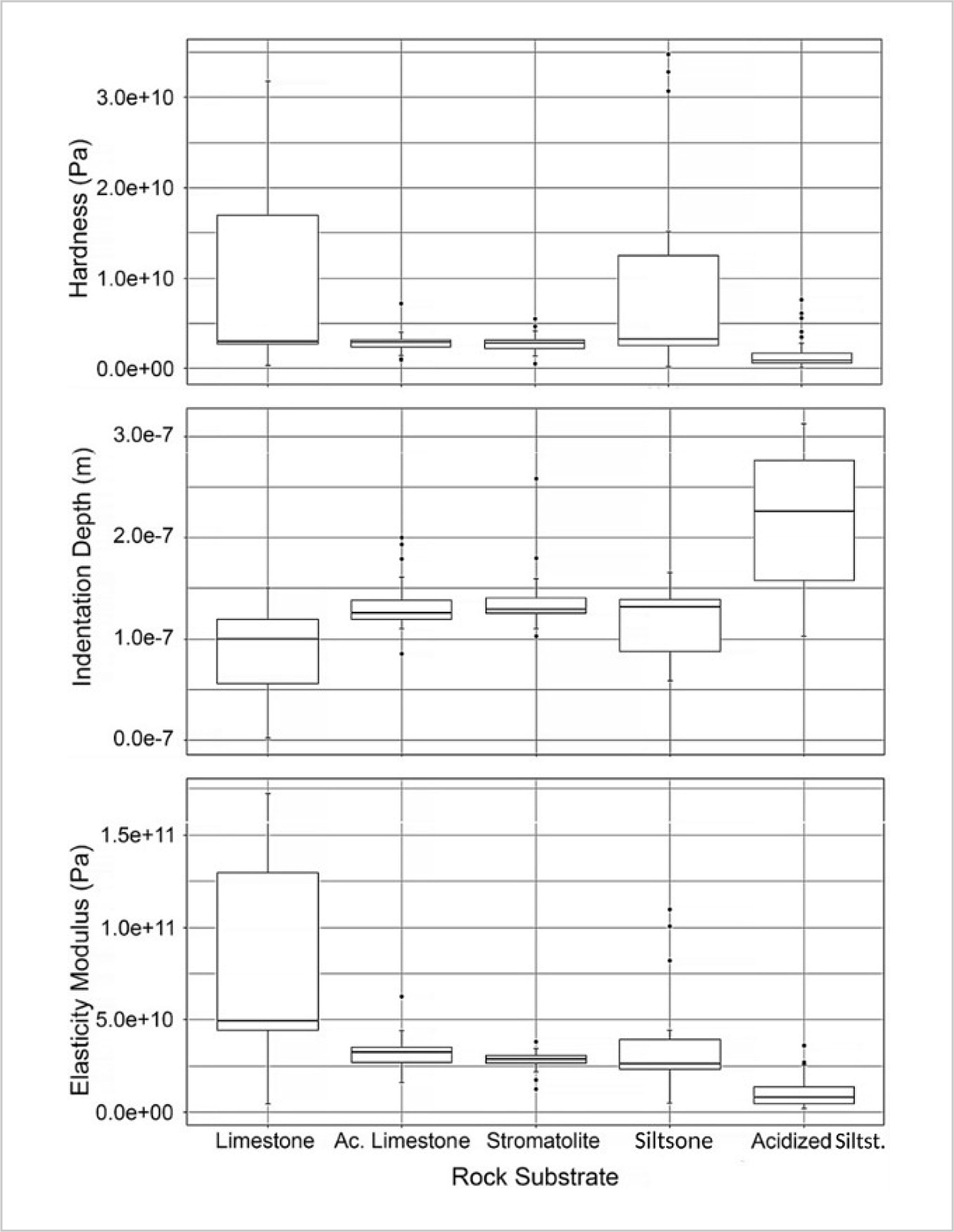
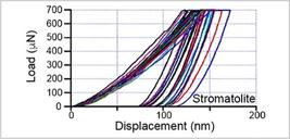
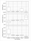
The nanoindentation was performed on the petrographic thin sections from Fig. 6, and the neo layers (B and C) were tested separately from the original matrix (A). The neo layers presented deeper indentation depths compared to the original rock matrices, confirming weaker mechanical properties, as is observable in Figure 9 and Figure 10. The stromatolite was the only rock that did not present neo layers resulting from the acidizing process (Figure 11).


Load-depth curves for the siltstone and its respective acidized surface (neo layers B and C).
The siltstone was the type of rock most affected by the acid attack. The indentation curves for neo layers B and C (Figure 9) reached depths up to 500 nm and showed large creep displacements (plateaus). As the plateaus on top of the indentation curves increase, the Young´s (elasticity) modulus and hardness decreases indicating that the samples become softer (Liu et al., 2018).
A box and whisker plot for hardness, indentation depths, and Young´s modulus resulting from the nanoindentation curves is presented in Figure 12.
4.6 Proppant Embedment and fracture conductivity decline
The proppant embedment tests used SinterBall Bauxite (HSP) 20/40 (425-850 μm), at 10.00 Kg/m2 (2.0 lb/ft2) proppant concentration, for 8 hours under a pressure of 40 MPa (5800 psi). The proppant was provided free of charge by Mineração Curimbaba.
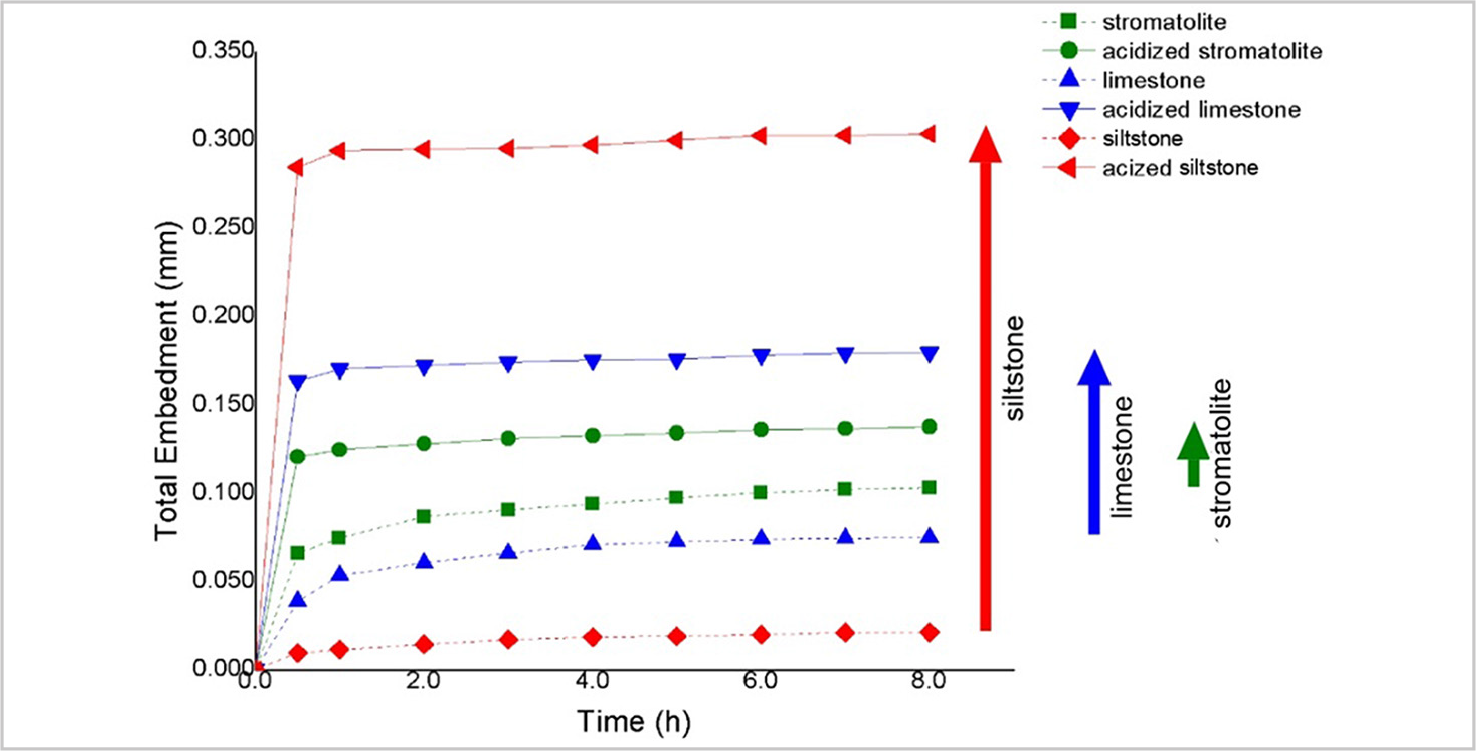
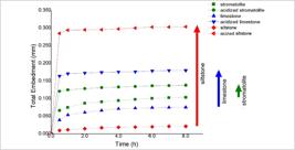
Proppant embedment values were determined by measuring the total axial compression of pairs of non-acidized and acidized rock waffles (Figure 5), compressing the proppant package between them, and comparing to the total axial compression of non-acidized pairs without proppant.
In Figure 13, it is possible to observe that the acidized siltstone presented the highest values for proppant embedment. This was in fact already expected, as the acidized siltstone presented the thickest set of neo layers. The acidized stromatolite without neo layers, on the other hand, presented the lowest value for proppant embedment among the acidized specimens. Finally, the acidized limestone, containing only the recrystallization neo layer C, an intermediate situation between the acidized siltstone and the acidized stromatolite, also presented an intermediate value for the proppant embedment.
The decline in fracture conductivity for the acidized siltstone, limestone and stromatolite is presented in Table 4. It was calculated with Equation 1 using the proppant embedment results in Figure 13 (at 8h) together with the proppant permeability information from the proppant manufacturer’s website (www.curimbaba.com.br). The Siltstone presented the highest value of fracture conductivity decline and the stromatolite presented a minimum value of less than 1%. The small decline in the stromatolite was not caused by the presence of neo layers, but rather by the crushing of the rough surface texture resulting from its high dissolution rate.
5. Conclusions
The combination of acidizing and hydraulic fracturing can increase the stimulated reservoir volume in oil and gas reservoirs, since the acid solution can reach and stimulate the microfracture network far beyond the main propped fracture, reaching distances within the reservoir horizon that the proppant is not able to do.
The microscopic and nanoindentation analysis of rocks associated with a tight gas reservoir in the Bambuí Group, of the São Francisco Basin, in Minas Gerais, revealed that the reservoir rock, the stromatolite, in contrast with the gas-generating rocks, does not produce weak neo layers resulting from the acid attack which are responsible for the increase in proppant embedment and loss of fracture conductivity. Conveniently the gas-generating rocks, that bound the reservoir rock, would be ultimately unaffected by hybrid fracturing as they have lost its gas to the reservoir rock over millions of years.
Therefore, proppant-acid fracturing, a hybrid stimulation, is the technique of choice recommended for the tight gas reservoirs in the Bambuí Group and those analogue to it.
-
Funding information
There are no funders to report for this submission.
Data availability
The authors state that this manuscript is based on the Doctorate's Thesis of Humberto Almeida Oliveira, entitled "Aplicação combinada de fraturamento hidraúlico e acidificação para estimulação de depósitos de gás não convencionais da Bacia do São Francisco," presented in 2023 at the Federal University of Minas Gerais, in the Graduate Program in Mining Engineering (DeMin, UFMG), with all data available at the following link: http://hdl.handle.net/1843/54824.
References
-
ALKATTAN, M. et al. An experimental study of calcite and limestone dissolution rates as a function of ph from -1 to 3 and temperature from 25 to 80 degrees c. Chemical Geology, 151, 199-214, 1998. DOI:10.1016/ S0009-2541(98)00080-1.
» https://doi.org/10.1016/S0009-2541(98)00080-1 -
AVILA, R. et al. Nota técnica n° 16/2020/sdb/anp-RJ: estudo realizado pela equipe da SAG para o subcomitê II REATE (programa de revitalização da atividade de exploração e produção de petróleo e gás natural em áreas terrestres), 2020. DOI:10.13140/RG.2.2.33384.70404.
» https://doi.org/10.13140/RG.2.2.33384.70404 - AZEVEDO, et al. Challenges faced to execute hydraulic fracturing in Brazilian pre-salt wells. In: US ROCK MECHANICS SYMPOSIUM, 44, US-Canada, 2010. Rock Mechanics Symposium, American Rock Mechanics Association.
- BANDARA, K. et al. Improved understanding of proppant embedment behavior under reservoir conditions: a review study. Powder Technology, 2019.
- BORTOLON NETO, L. et al. Conductivity and performance of hydraulic fractures partially filled with compressible proppant packages. International Journal of Rock Mechanics and Mining Sciences 74, 1-9, 2015.
- CARDWELL, P. H. et al. Well treatment. US Patent 2,802,531, 1957.
-
CHE, M. et al. Propped fracturing in deep naturally fractured tight carbonate reservoirs, 2018. DOI:10.2118/191712-18RPTC-MS.
» https://doi.org/10.2118/191712-18RPTC-MS. - CHEN, D. et al. A permeability model for the hydraulic fracture filled with proppant packages under combined effect of compaction and embedment. Journal of Petroleum Science and Engineering 149, 428-435, 2017.
-
CHEN, X. et al. Hydraulic, acid, and proppant-carrying acid fracturing stimulation of volcanic reservoirs in Sichuan basin, China: an experimental study. Petrol. Science and Technology 41,731-749, 2023. DOI: 10.180/10916466.2022.2070207.
» https://doi.org/10.180/10916466.2022.2070207 -
CURIMBABA. Data sheet técnico SinterBall bauxite (HSP). Curimbaba, 18 Apr. 2018. Disponível em: https://www.curimbaba.com.br/admin/media/uploads/produtosItens/c-a-sinterball-bauxite-bt430091-port-curimbaba.pdf. Acesso em: 21 jun. 2024.
» https://www.curimbaba.com.br/admin/media/uploads/produtosItens/c-a-sinterball-bauxite-bt430091-port-curimbaba.pdf - GAO, Y.; LV, Y.; WANG, M.; LI, K. New mathematical models for calculating the proppant embedment and conductivity. In: IPTC - INTERNATIONAL PETROLEUM TECHNOLOGY CONFERENCE, European Association of Geoscientists & Engineers. p. Cp-350, 2013.
- GUO, J. et al. Comprehensive study of fracture flow characteristic and feasibility of hybrid volume stimulation technique in tight fractured carbonate gas reservoir. Journal of Petroleum Science and Engineering 174, 362-373, 2019.
-
HU, B. et al. The effects of hydrochloric acid pretreatment on differ-ent types of clay minerals. Minerals 12, 1167, 2022. DOI: 10.3390/min12091167.
» https://doi.org/10.3390/min12091167 - LI, C. et al. Indentation creep behavior of Fe-based amorphous coatings fabricated by high velocity oxy-fuel. Journal of Non-Crystalline Solids, 503, p. 62-68, 2019.
- LIU, K. et al. Application of nanoindentation to characterize creep behavior of oil shales. Journal of Petroleum Science and Engineering 167, 729-736, 2018.
-
MUMALLAH. Factors influencing the reaction rate of hydrochloric acid and carbonate rock. SPE - INTERNATIONAL CONFERENCE ON OILFIELD CHEMISTRY, 1991. DOI:10.2118/21036-MS. sPE-21036-MS.
» https://doi.org/10.2118/21036-MS.sPE-21036-MS - OLIVER, W. C.; PHARR, G. M. An improved technique for determining hardness and elastic modulus using load and displacement sensing indentation experiments. Journal of Materials Research 7, 1564-1583, 1992.
- SANEMATSU, P. et al. Image-based stokes flow modeling in bulk proppant packages and propped fractures under high loading stresses. Journal of Petroleum Science and Engineering 135, 391-402, 2015.
- SHI, X. et al. Application of nanoindentation technology for characterizing the mechanical properties of shale before and after supercritical CO2 fluid treatment. Journal of CO2 Utilization 37, 158-172, 2020
- SMITH, M. B. et al. Simulation, design, and application of acid + proppant stimulation in a carbonate reservoir. In: SPE - INTERNATIONAL HYDRAULIC FRACTURING TECHNOLOGY CONFERENCE AND EXHIBITION, Society of Petroleum Engineers. p. 1-16, 2018.
- VIEIRA, L. C. et al. A formação Sete Lagoas em sua área-tipo: fácies, estratigrafia e sistemas deposicionais. Revista Brasileira de Geociências 37, 1-14, 2007.
-
WAN, C. et al. Effect of carbon nanoparticles on the crystallization of calcium carbonate in aqueous solution. Nanomaterials (Basel). 1, v.9, n. 2, p. 179, Feb. 2019. DOI: 10.3390/nano9020179. PMID: 30717114; PMCID: PMC6409635.
» https://doi.org/10.3390/nano9020179 - ZHANG, L. et al. A new method to improve long-term fracture conductivity in acid fracturing under high closure stress. Journal of Petroleum Science and Engineering 171, 760-770, 2018.
-
Associate Editor
Ricardo Cabral de Azevedo

 Group in the São Francisco basin. Carbonates from the upper part of the Sete Lagoas Formation, represented by the biogenic carbonates known as stromatolites, make up the main gas reservoir in the Bambuí Group (Ávila et al., 2020).
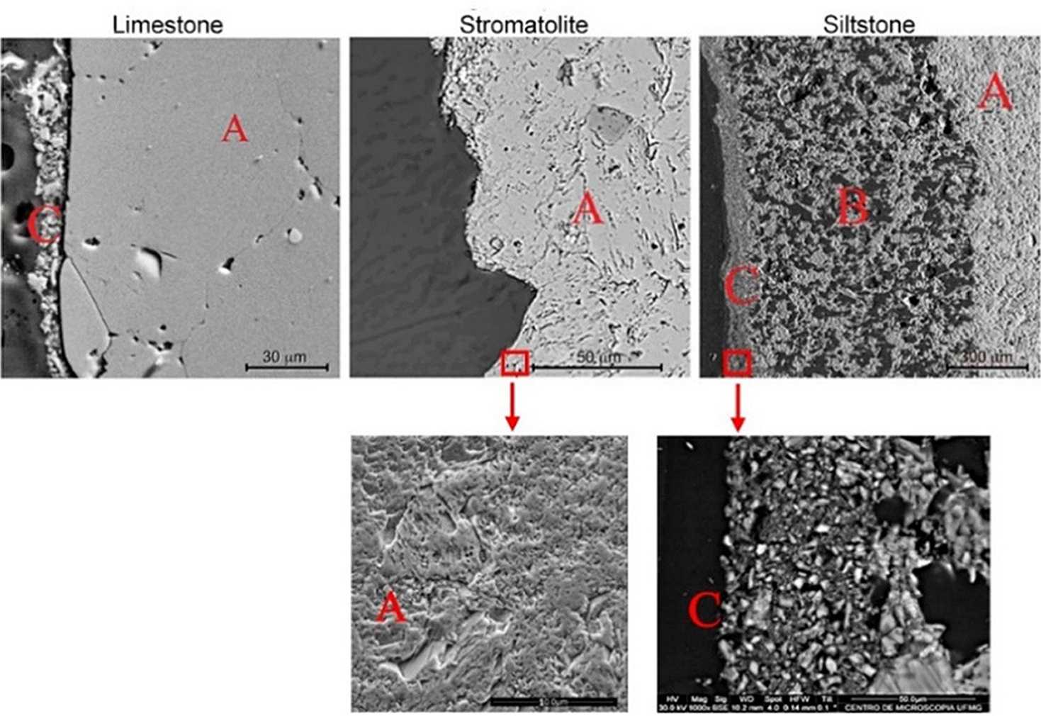 Notice the micropores in the stromatolite and the crystals from neo layer C in the siltstone.
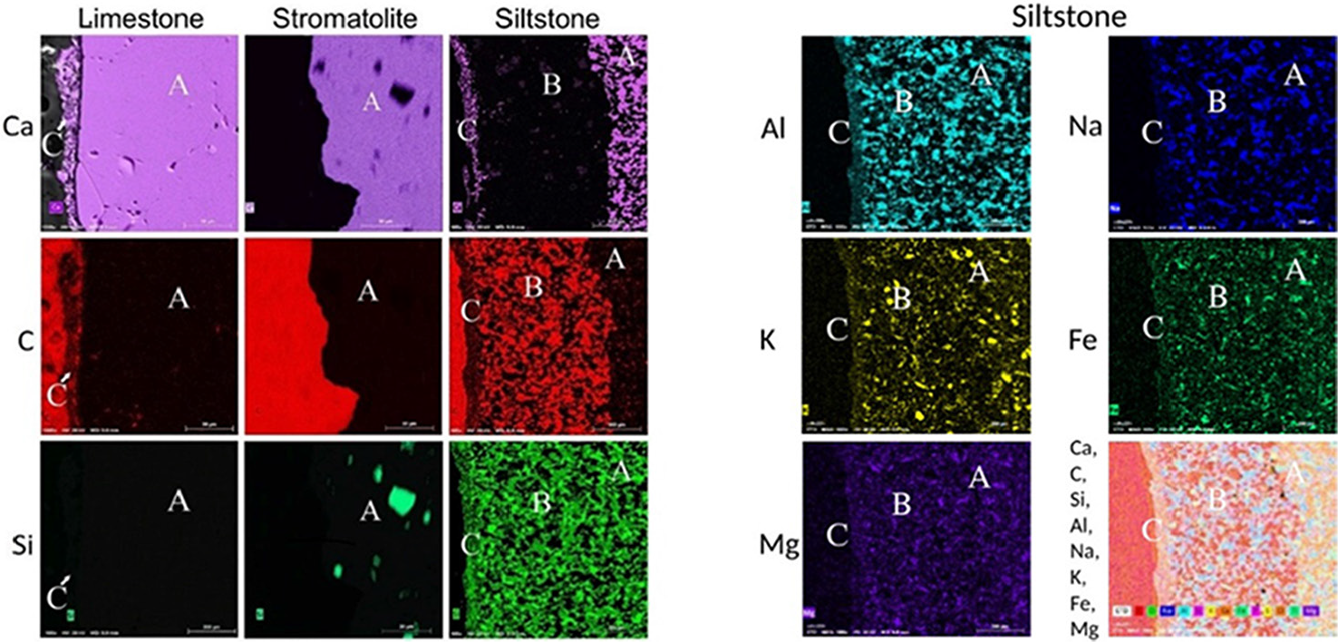 Right - EDS mapping for K (muscovite), Na (albite), Fe & Mg (chamosite), and Al (muscovite, albite, chamosite) in the siltstone.


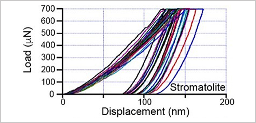 Unlike the previous two cases, the stromatolite did not present neo layers resulting from the acid etching.