 Structural behaviour of composite bridge deck with PMC link slabs reinforced with GFRP bars
ABSTRACT
The structural behavior of composite bridge decks with link slabs is the subject of this study. The purpose of this investigation is to solve difficulties such as water leakage, joint dislocation, and corrosion. Water leaking at joints is a common problem in bridges, regardless of whether they have a single span or numerous spans. This can cause a variety of components to deteriorate over time. According to the findings of this study, the replacement of expansion joints with link slabs is advised as a means of mitigating these concerns. The integration of link slabs at the internal joints of bridge decks is intended to result in the creation of jointless bridges. Nevertheless, they are subjected to extra strains as a result of temperature, creep, and shrinkage, which ultimately results in surface cracks and corrosion. GFRP bars and debonding principles are utilized in the design process of link slabs according to this perspective. In addition, Polymer Modified Concrete (PMC) is utilized in order to improve the longevity of concrete as well as its structural strength. In this study, experimental analysis is carried out to evaluate the mechanical characteristics of PMC concrete as well as the structural behavior of composite bridge decks that contain link slabs. A total of three specimens were cast with a ratio of 1:4 in order to investigate the structural behavior of link slabs. The findings offer insights into the ideal design parameters for composite bridge decks, which contribute to improvements in the performance and durability of bridges.
Link Slab; Load Deflection; GFRP; Crack Behaviour; Stiffness
1. INTRODUCTION
The Bridges are designed as single span or multiple span composite bridges with support structures. The joints in the bridges will cause the leakage of water which leads to the deterioration of bridge girder, bearing and supporting piers. During earthquakes, the dislocation of joints and girders is more common in the recent years [1]. To avoid this condition, it is recommended to reduce more number of expansion joint by replacing 60% of joints with link slabs [2]. The jointless bridges were designed by introducing link slab in the interior joints of bridge decks [2, 3]. The additional stresses imposed on the link slabs due to temperature, creep and shrinkage develops the cracks on the surface of link slabs. And, this will leads to the corrosion on reinforced bars and steel girders. To resist this condition, the link slab are designed by using steel reinforcement bars coated with epoxy [4,5,6,7]. This epoxy coating was used to avoid the reinforcement corrosion in link slabs. The debonding concept in the link slab was designed to reduce the stiffness and minimize the developed stress in the link slabs. Initially, the old bridges were retrofitted with link slab to reduce the seismic damages and maintenance cost [3, 8]. The above methods will have shortfall on formation of cracks in the concrete surface. The researchers developed the alternatives for concrete in link slab and they introduced the Engineered cementitious composites to increase the life cycle of concrete and have high corrosion resistance behaviour [9,10,11,12,13,14,15]. The ECC were developed to reduce the crack width limited to 60 to 80µm and exhibit the ductile behaviour of concrete [16,17,18,19]. The micro structural ECC concrete were formed by different proportion of material to improve the structural performance and life cycle of link slabs. During initial ECC, PVA fibre was used along with foundry sand and later, it was replaced with waste materials & recycled products [20,21,22]. This was further developed as high performance fibre reinforced Engineered cementitious composites using waste products and recyclable materials [23, 24].
The FRP laminates was used to strengthen the bridge girders and beams during maintenance of bridges and concrete structures. This will improve the flexural behaviour and shear capacity of the the structures [6, 15, 25,26,27,28,29]. The use of composite system such as FRP grid and bars will increase the load carrying capacity and have control in cracking on concrete surface [30, 31]. The use of GFRP bars in the construction is increased in the recent years due to its Anti-corrosion behaviour and strength parameters.
Due to these advancements, the use of traditional ECC and FRP materials often faces problem related to cost and constructability. To address this, Polymer Modified Concrete (PMC) has gained attention as a cost-effective and alternative durable material for link slabs. The acrylic based polymer modified concrete mixes enhance the impermeability, crack resistance, and bonding performance of concrete, and make them suitable for long-term bridge deck applications [32,33,34,34]. The use of PMC with GFRP reinforcement combines the benefits of both materials and improving flexural capacity while mitigating corrosion-related deterioration [27, 28, 35].
2. MATERIALS AND METHODOLOGY
2.1. Materials
2.1.1. Cement
The materials used consist of Portland Pozzolana Cement (PPC), per IS 1489(Part 2) in this experiment. The durability and resistance to environmental influences of cement are enhanced by the addition of pozzolanic ingredients. PPC exhibits good compressive strength, particularly over time, as the pozzolanic elements respond to the lime produced during hydration. Concrete becomes more workable owing to pozzolanic compounds, generating mixing and placement easier.
2.1.2. Fine aggregate
The M-Sand is passing through a sieve size of 4.75 mm sieve is used as a fine aggregate and crushed stone with a maximum size of 20 mm is used as coarse aggregates.
2.1.3. Water
Clean water was utilized for mixing and curing purposes. The water used was free from organic substances, oils, and other contaminants that could hinder the setting and strength development of cement.
2.1.4. Polymer
An acrylic-based liquid polymer was incorporated into the concrete to improve adhesion, water resistance, and overall mechanical properties [35,36,37,38]. The polymer was used in emulsion form and its properties listed in Table 1.
2.1.5. GFRP rebar
The 8 mm GFRP bars used in this study were tested in the Universal Testing Machine (UTM) to determine their tensile properties, including ultimate strength, elastic modulus, and rupture strain. The measured properties of the 8 mm GFRP bar shown in Table 2 are in close agreement with the findings reported by [10, 11, 22, 25], who observed similar mechanical behaviour for E-glass fibre–reinforced polymer rebar embedded in concrete.
2.2. Mix design
The mix design for the study was designed to produce polymer-modified concrete using grade M40 Portland Pozzolana Cement (PPC) at a 1:1.6:2.43 ratio. According to IS 10262:2019, the design aimed for a maximum water-to-cement ratio of 0.45. In this Study, the acrylic polymers were added with varying percentages of 5, 10, 12, 15, 20 by weight of cement to determine the optimum percentage. The selected polymer dosages of 5%, 10%, 12%, 15%, and 20% by weight of cement were chosen based on trends reported in previous optimization studies on polymer-modified concrete [10, 22, 23, 39]. Earlier works by [10, 22] demonstrated that acrylic and latex-based polymer additions in the range of 5–20% significantly improve the tensile strength, impermeability, and crack resistance of cementitious composites without adversely affecting workability. Accordingly, this study adopted incremental variations within this established range to identify the optimum polymer percentage for the PMC mix used. The different mix proportions were shown in Table 3.
2.3. Mechanical property test
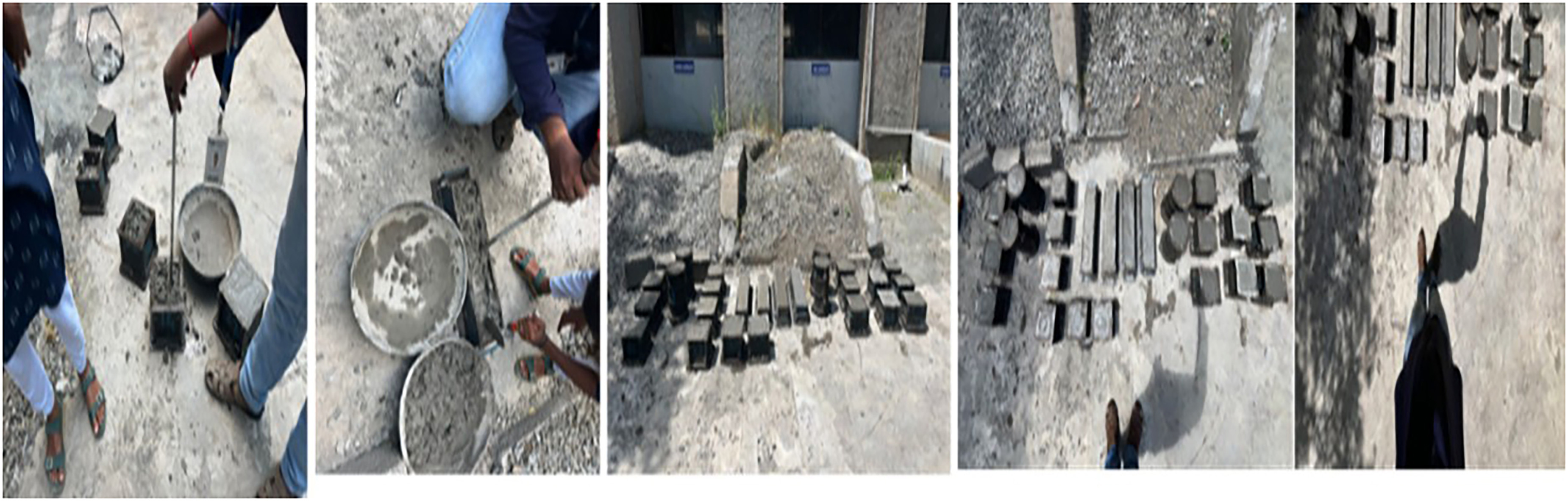
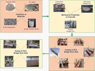
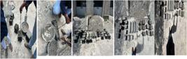
The polymer-modified concrete study’s specimens were prepared and cast with great care to guarantee the accuracy and consistency of the findings. The required quantities of cement, fine, and coarse aggregate were carefully weighed in compliance with the determined 1:1.6:2.43 mix ratio. In a concrete mixer, the dry ingredients were combined for three to five minutes to guarantee a uniform distribution. The water soluble acrylic polymer and clean potable water were then progressively added to the dry mixture. to ensure that the mixture was uniform, workable, and free of any remaining clumps or dry areas. The Specimen were casted with the size of 150 mm × 150 mm × 150 mm cubes, 150 × 300 mm cylinder and 150 mm × 150 mm × 500 mm prism were casted as shown in Figure 1.
2.4. Experimental investigation of bridge deck slab
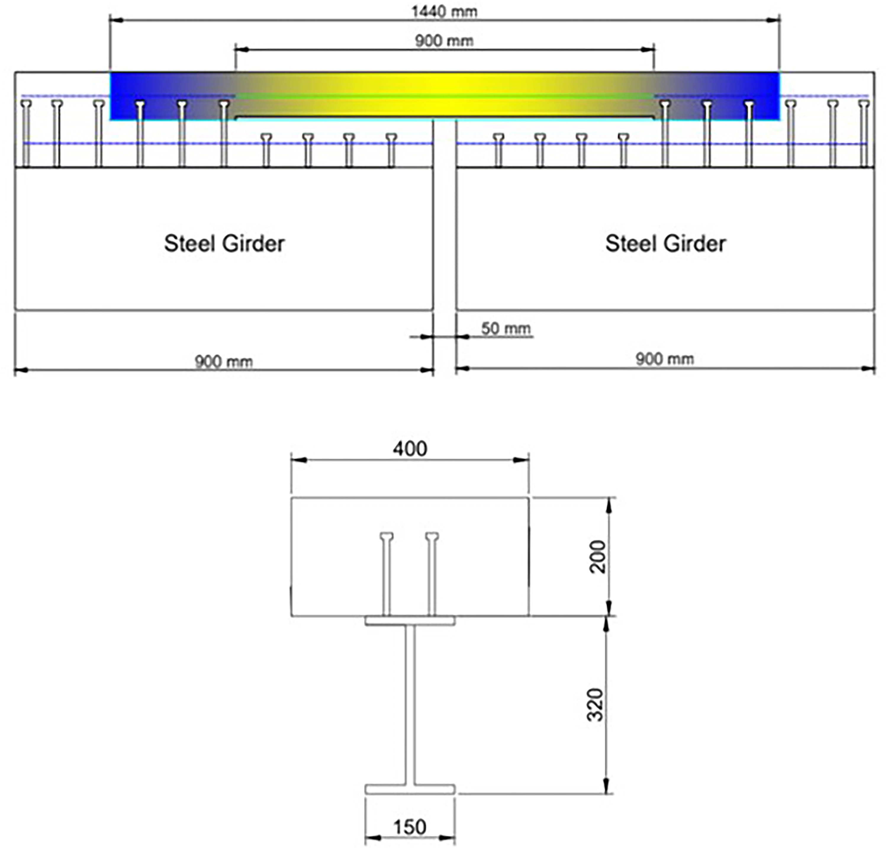
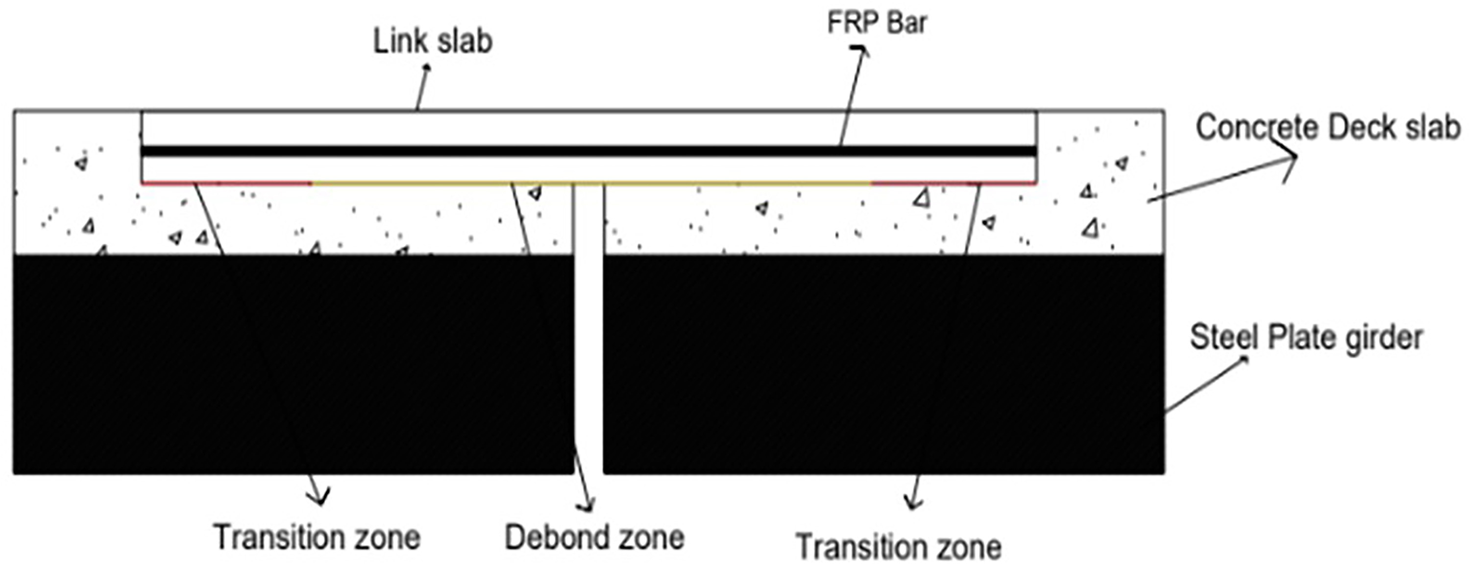
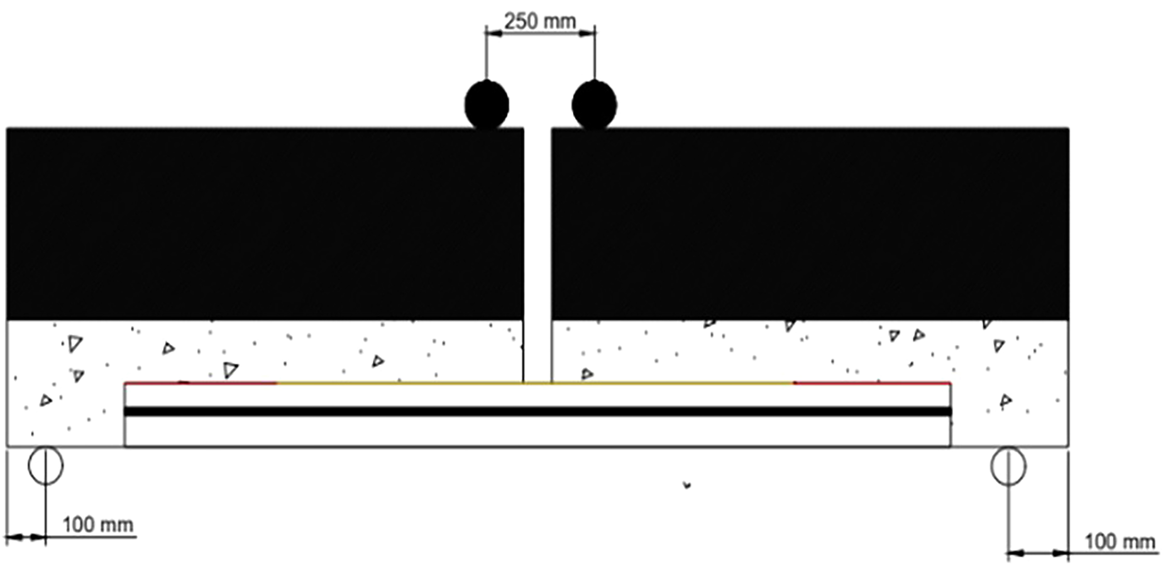
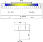
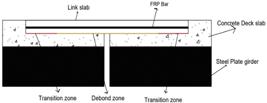
The span of the bridge is 18 m. The one –fourth scale of the bridge deck is taken for experimental analysis [40]. The size of the link slab is kept as original size to study the structural behaviour of deck slab with link slab. The span of the link slab is taken as 1.44 m as shown in Figure 2. The span of the link slab is designed as debonded zone and transition zone. The link slab is not bonded to the top flange of the girder by shear connector which is designed as 5% of span length as debonded length [41,42,43] and 2.5% of span length as transition zone in link slab considering overall system behaviour [16, 39, 44]. The deck slab was casted with a mix ratio of 1:1.6:2.43. The moulding is attached at the flange of the plate girders to ensure the proper casting at the bottom of the slab. The thickness of deck slab is designed as 200 mm as shown in Figure 3.
2.4.1. Casting of I-section plate girders
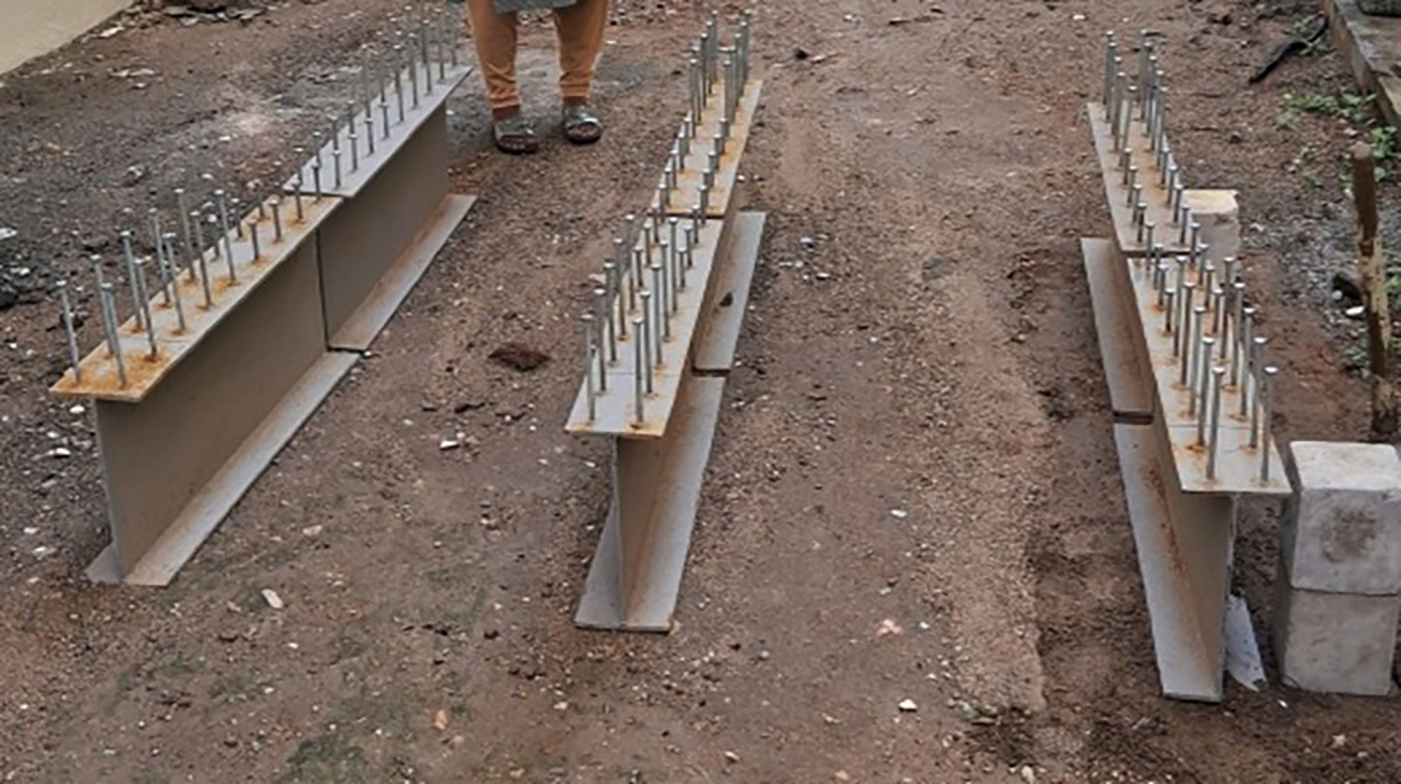
The I section plate girder was welded by joining two flanges of 150 mm × 10 mm steel plates and web of 300 mm × 10 mm steel plate is shown in Figure 4. The two I section steel girder was created with the spacing of 50 mm with the top and bottom flange as 150 mm with thickness of 10 mm. and web of 300 mm × 10 mm. The shear connectors are welded to the top face of the flange to bridge connections between the plate and deck slab [45, 46].

2.4.2. Casting of deck slab
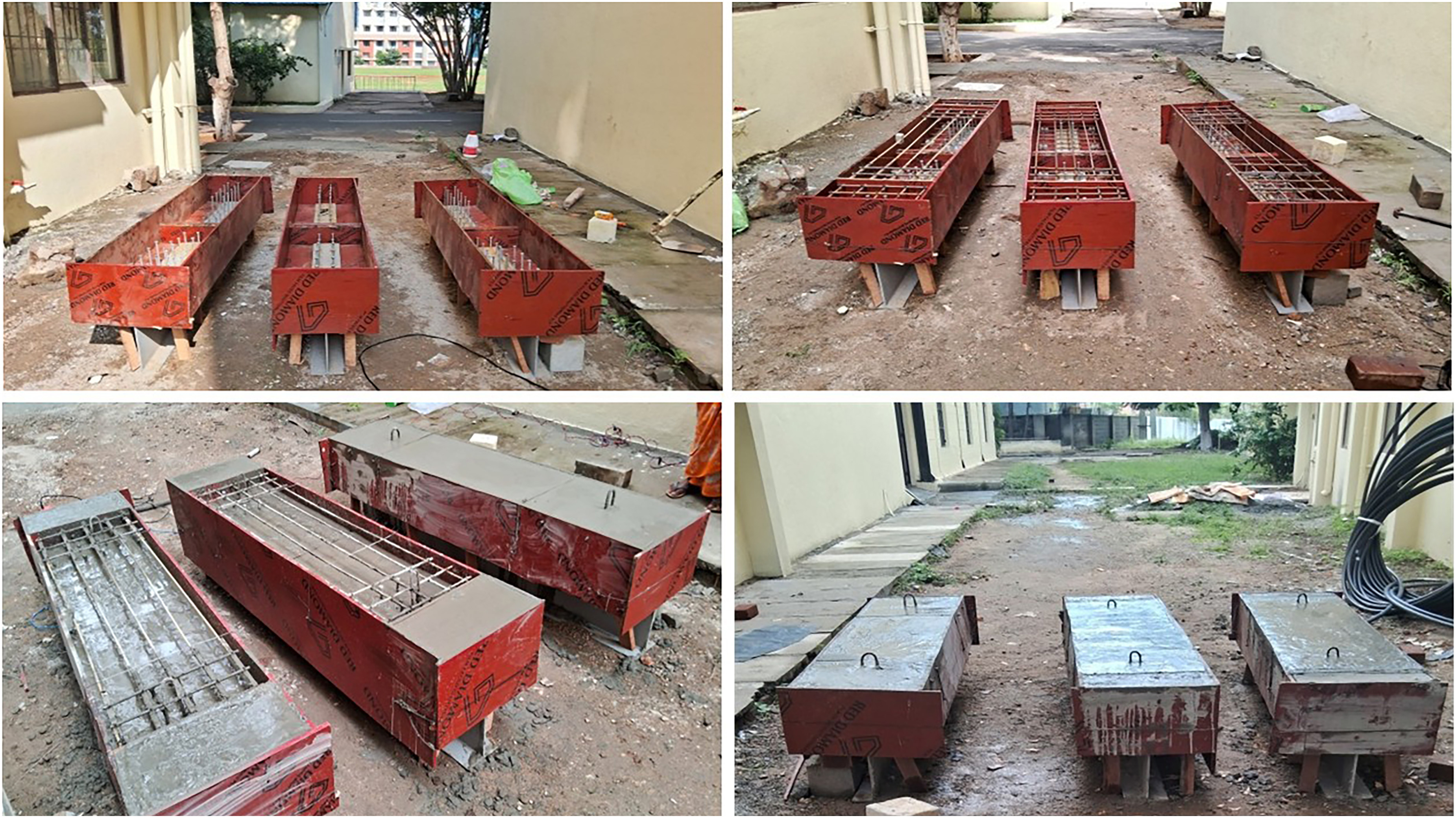
The deck slab was casted with a mix ratio of 1:1.6:2.43. The moulding is attached at the flange of the plate girders to ensure the proper casting at the bottom of the slab. The thickness of deck slab is designed as 200 mm. The spacing of 50 mm is provided between the two 900 mm span I section plate girder to cast deck slab. The depth of the link slab will be taken as 100 mm as per the recommendation from previous studies [43, 47]. The length of the link slab is 1.44 m with 900 mm as deboned zone. The total of three specimen were casted were shown in Figure 5. The Specimen LS1 is casted as RCC Bridge Deck with RCC link slab and steel Reinforcement, LS2 as RCC Bridge Deck with PMC link slab and Steel Reinforcement and LS3 as RCC Bridge Deck with PMC Link slab and GFRP Reinforcement. 15 percentage of acrylic polymer is found as optimum from the mechanical properties test and it will be used for casting of PMC Link slab.

3. EXPERIMENTAL SETUP
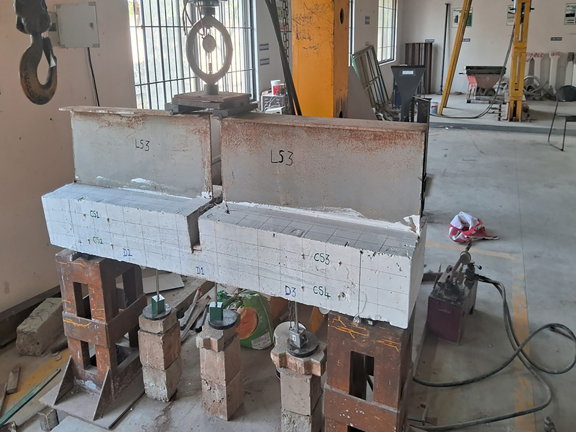
The three specimens LS1, LS2 and LS3 were tested under inverted configuration, in line with previous experimental setups [43, 48]. The support conditions were provided at 100 mm from each end to simulate realistic boundary conditions, and cyclic loading was applied until structural failure. The load cell of 200 kN capacity is attached to apply the cyclic loading. The three dial guage D1, D2 and D3 were used to determine the deflection of the deck slab. The D1 was fixed at the middle while the D2 and D3 were fixed at 1/4th of the span of the deck slab at each side [2, 4, 49]. The Cyclic loading was applied as given in Figures 6 and 7.
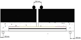

The experimental investigation was done by testing three specimen in which each specimen reflects a distinct configuration, LS1-RCC deck slab with steel reinforcement, LS2-PMC slab with Steel reinforcement and LS3-PMC slab with GFRP reinforcement. This methodology was adopted to capture the diverse strurural behavioural of deck slab under flexural loading. This approach was adopted to found the clear comparative performance trends rather than statistical generalizations. The specimen size and scale were selected to balance the accuracy of the experiment with resource optimization ensures that the model geometry and boundary condition to represent the actual bridge link slab behaviour. The use of a 1/4th scale model is a widely accepted experimental study for bridge deck studies as demonstrated by [2, 4, 24], who confirmed that this reduced-scale models can accurately reproduce stiffness, cracking characteristics, and failure mechanisms of the prototype. The limited number of specimen restricts the full statistical evaluation and the large scale representative testing remains essential for validating the deformation modes, stiffness degradation and crack propagation phenomenon which are difficult to replicate through numerical or analytical methods.
4. RESULT AND DISCUSSION
4.1. Compressive strength test
Compressive strength tests were conducted in accordance with IS 516:1959, using a loading rate of 140 kg/cm2 per minute, applied gradually until failure occurred. For each mix variation—including 0% (control), 5%, 10%, 12%, 15%, and 20% polymer addition—three cube specimens were tested to ensure result reliability and reproducibility. The compressive strength for each cube was determined by dividing the maximum failure load by the cross-sectional area of the specimen. The test results, presented in Figure 8, shows the compressive strength of M40 grade concrete improves with increasing polymer content up to a certain point. The optimum range appears to be between 10% and 12% polymer addition [32], where the average compressive strength peaked, exceeding that of the control mix by a noticeable margin. Beyond this range, particularly at 15% and 20%, a gradual reduction in compressive strength was observed, which may be attributed to an excess of polymer disrupting the cement matrix, reducing the density and bond strength within the concrete. The control mix (0% polymer) achieved compressive strengths in the range of 38–40 MPa, while mixes with 10–12% polymer reached values of approximately 45–46 MPa, demonstrating a 15–20% increase in strength compared to the base mix. At 20% polymer, however, the strength reduced to nearly the same as the control. The mathematical equation for average compressive strength with various percentage of polymer is give in the equation 1 with R2 = 0.9996.
4.2. Tensile strength test
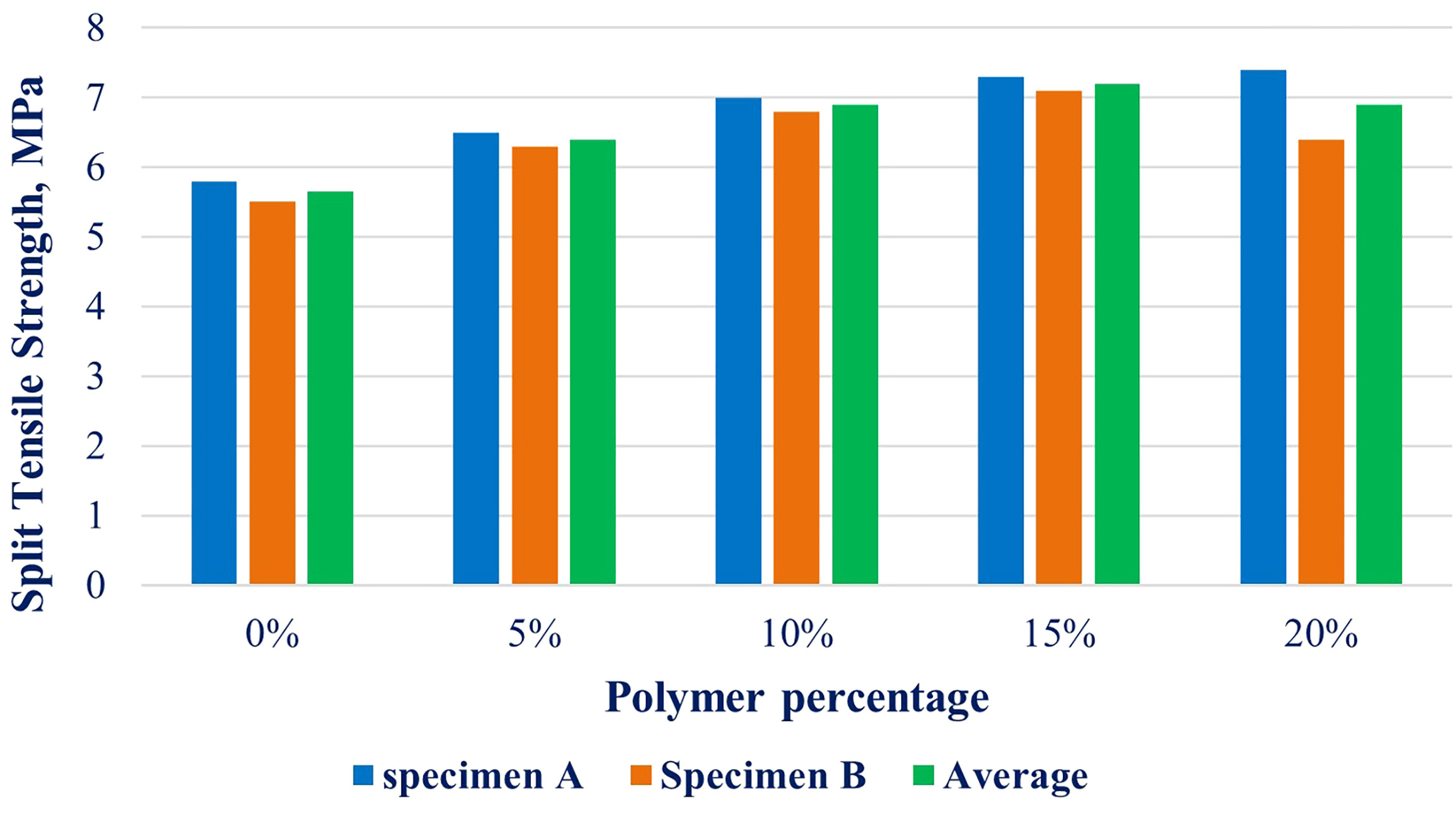
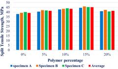
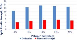
The tensile strength of the prism with size 150 × 150 × 500 mm were tested under two point loading for the polymer percentage 5%, 10%, 12%, 15% and 20%. The tensile strength of the specimen increases with the increase of polymer percentage which suggests that the polymerization enhances the concrete resistance to tensile stress. This polymerization bridging the micro cracks and forms the internal microstructural link between aggregates and cement paste. The first benefit of polymer modification is demonstrated by the slight increase in tensile strength at 5% polymer addition. The control mix got the tensile strengths of 5.8 MPa and 5.5 MPa. The addition of 5% polymer improves the strength to 6.5 MPa and 6.3 MPa, confirming that even a modest dosage of polymer increases the crack bridging and matrix densification. The optimum percentage of 12% to 15% is found to enhance the properties of PMC concrete. The optimum performance was observed at 12–15% polymer where the tensile strengths increases up to 7.5 MPa at 12% and remained consistently high up to 7.3 MPa at 15% as shown in Figure 9. At 20% polymer, the tensile strength of the concrete specimen drops slightly from 7.4 MPa to 6.4 MPa which likely due to excess polymer interfering with cement hydration and bond formation that is observed in compressive strength results. The results suggest that the acrylic polymer enhances tensile strength primarily by bridging micro cracks and increasing ductility by improving the interface bond between cement paste and aggregates. The mathematical equation for split tensile strength of specimens is given in eqn. 2 with R2 = 0.9491.

4.3. Flexural strength test
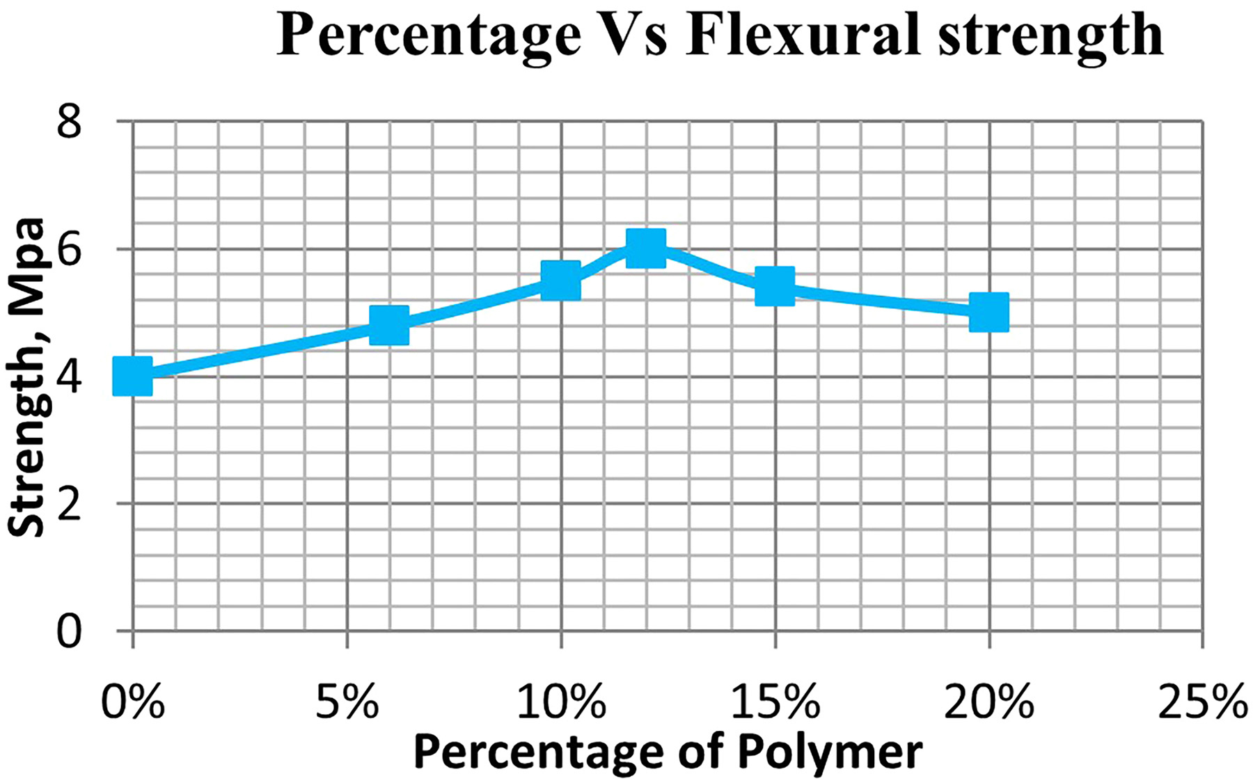
The flexural strength analysis of the polymer-modified M40 concrete demonstrates the impact of polymer content on the material’s ability to resist bending stress. Starting with the control specimen or conventional concrete specimen (0% polymer), the estimated flexural strength provides a baseline measurement of 4.0 MPa. Introducing polymer at low percentages begins to enhance the concrete’s flexural capacity. Figures 10 and 11 shows with an increase in replacement percentage of polymer, a significant improvement in flexural strength was noted up to 12% replacement, showing a 50% enhancement compared to the control. Beyond 12%, the strength began to decline slightly but remained higher than the control mix. This indicates that 12% replacement yielded the optimum flexural strength, demonstrating improved bonding and load transfer efficiency within the composite matrix. The Mathematical expression for various percentage of polymer is given equation 3 with R2 = 0.9536.

The long-term durability of polymer-modified concrete (PMC) is influenced by environmental exposure conditions such as moisture variation, ultraviolet radiation, and chloride ingress. Previous studies by LEPECH and LI [10] and ULKU et al. [39] reported that acrylic-based polymers substantially enhance resistance to water permeability, shrinkage cracking, and surface degradation under cyclic wet–dry and thermal conditions. Similarly, OZYILDIRIM and VIEIRA [22] demonstrated improved freeze–thaw stability and reduced chloride penetration in polymer-modified systems, confirming their suitability for bridge deck applications.
4.4. Load–deflection behaviour
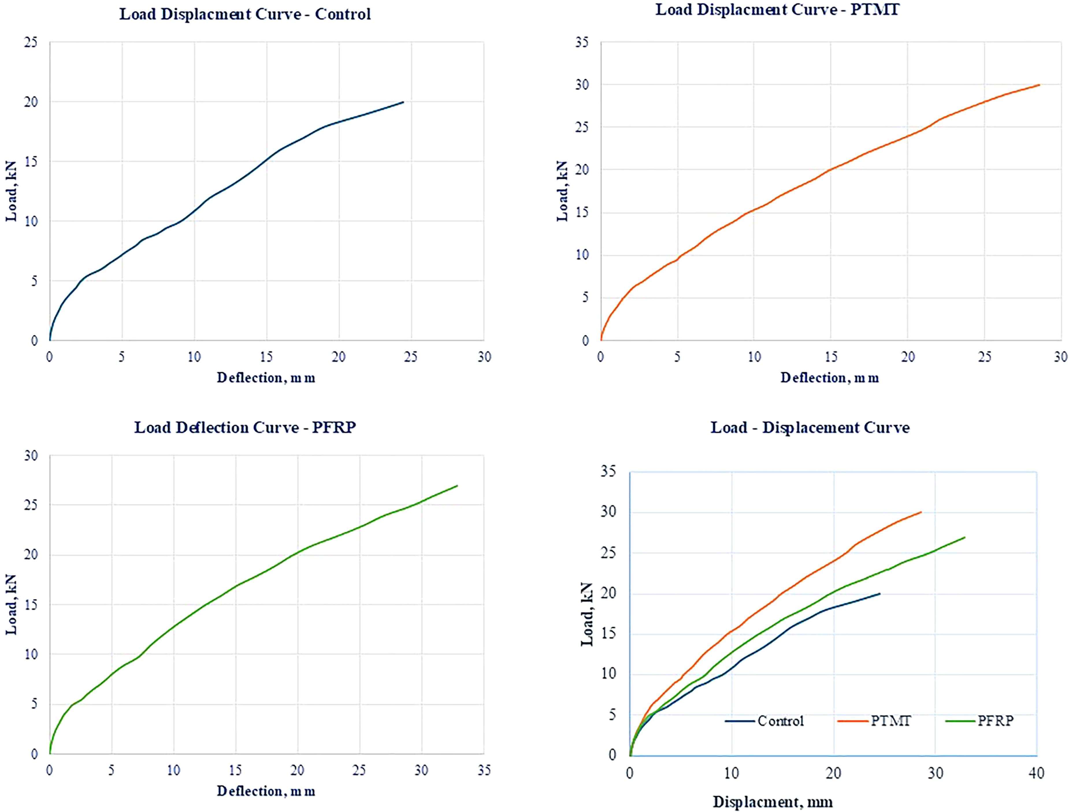
The load–deflection response of the bridge deck specimens under cyclic loading was evaluated to investigate the structural performance of link slabs reinforced with different materials [50,51,52,53,54,55] is plotted in Figure 12. All three specimens exhibited an initial linear load–deflection response up to a load of approximately 4.5 kN. In this phase, LS1 (Control) exhibited the highest initial stiffness, followed by LS2 and LS3. The stiffness in this range is primarily governed by the flexural rigidity of the link slab and the type of reinforcement material. The RCC link slab (LS1) with steel reinforcement showed a steeper slope, indicating a stiffer response due to the higher elastic modulus of steel compared to GFRP or the deformability of PMC.
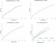
Beyond 4.5 kN, the curves began to diverge. LS2 and LS3 started exhibiting nonlinear behaviour at lower loads than LS1 due to early microcracking within the PMC. However, due to the strain-hardening nature of PMC and the distributed cracking behaviour, the specimens maintained load-carrying capacity with controlled deflection growth. LS1, despite its higher initial stiffness, began accumulating damage in a more localized manner, as reflected in its sharper curvature beyond 6 kN. In the final phase of loading, LS3 demonstrated superior ductility and deformation capacity as given in Table 4, reaching a maximum deflection of 32.8 mm at 27 kN, with continued load-bearing up to that point. LS2 showed a peak deflection of 28.53 mm at 30 kN, while LS1 reached a maximum deflection of 24.45 mm at 20 kN. This highlights the ability of PMC combined with GFRP reinforcement in LS3 to sustain higher deformation and absorb greater energy without brittle failure.
The extended deflection range of LS3 is attributed to the synergistic effects of the high tensile strain capacity of PMC and the elastic behaviour of GFRP, which together enable multiple fine cracks to develop and delay localization. In contrast, LS1 exhibited more brittle failure characteristics, with less deflection capacity and rapid stiffness degradation after peak load.
The load–deflection curves of the three specimens are presented in Figure 12. All curves exhibit a distinct multi-phase response that includes an initial elastic phase, a transition/cracking phase, and a final nonlinear failure phase. The polynomial regression equations for the three specimens are given in equation 3, 4 and 5 demonstrate high coefficients of determination (R2 > 0.998), indicating a strong correlation between applied load and vertical deflection throughout the loading regime. Equation 4 represents the load displacement behaviour of LS1 (RCC link slab with steel reinforcement) with, R2 = 0.9985. load displacement behaviour of LS2 (PMC link slab with steel reinforcement) is given in equation 5 with R2 = 0.9987, equation 6 represents the load displacement behaviour of LS3 (PMC link slab with GFRP reinforcement) with R2 = 0.9986
Among the specimens, LS2 and LS3 displayed superior deflection capabilities compared to LS1, indicating enhanced deformability due to the presence of PMC in the link slab. Notably, LS3, which incorporated GFRP reinforcement, exhibited the most ductile behaviour and distributed deformation over a wider range of deflections. This behaviour can be attributed to the synergistic interaction between the high strain capacity of PMC and the elastic nature of GFRP bars, leading to gradual stiffness degradation and sustained load resistance during cyclic loading. In contrast, LS1 demonstrated higher initial stiffness due to the use of conventional RCC and steel reinforcement but experienced earlier onset of cracking and a more abrupt progression toward failure. The concentration of deformation and crack localization near the center of the slab in LS1 suggests limited energy dissipation capability compared to the PMC-based link slabs. The experimental findings confirm that link slabs constructed with PMC and FRP reinforcement (LS3) are more effective in enhancing the flexural performance and serviceability of jointless bridge decks. These results validate the potential of such configurations in extending the functional lifespan of bridge systems while mitigating maintenance challenges associated with traditional expansion joints.
4.5. Stiffness degradation behaviour
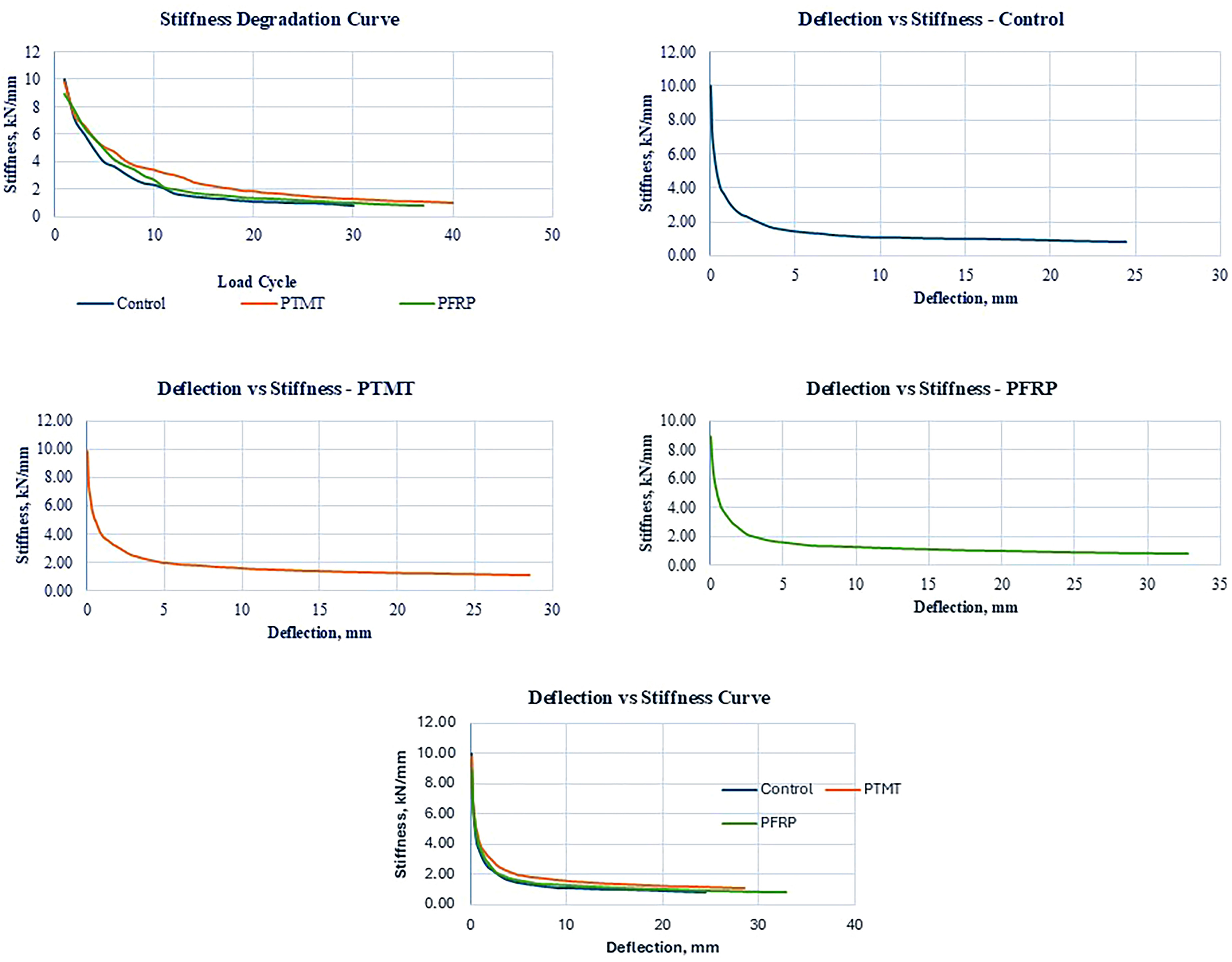
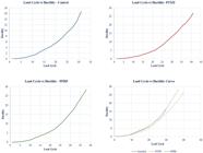
Stiffness degradation was studied to evaluate the loss in structural rigidity of the specimens under progressive cyclic loading. Stiffness is defined as the ratio of applied load to the corresponding deflection at mid-span, and its degradation is a critical parameter in assessing the durability and residual performance of the link slab systems over repeated service loads. The stiffness values were derived at each load increment and plotted against the number of load cycles with polynomial regression curves fitted to describe the degradation trends for each specimen is shown in Figure 13. The load cycle and stiffness degradation behaviour of the three specimens LS1, LS2 and LS3 is represented by the following regression equations 7, 8 and 9 respectively with R2 = 0.9945, R2 = 0.9932, R2 = 0.999.

LS1 showed the fastest degradation in stiffness among the three specimens. The initial stiffness of 10 kN/mm reduced significantly as the loading progresses which indicate the rapid cracking and stiffness loss in the RCC link slab. LS2 specimen exhibited the improved stiffness retention over the LS1 specimen that attributable to the improved crack bridging capability and ductile behaviour of the polymer modified concrete. The initial stiffness of 9.80 kN/mm gradually reduced under cyclic loading which maintains the more stable stiffness profile. The specimen LS3 demonstrated the most favourable stiffness degradation profile. Even though a slightly lower initial stiffness value of 8.92 kN/mm, the specimen retained its stiffness over a longer range of application of load. The presence of GFRP reinforcement along with PMC provides a more distributed cracking pattern and delayed stiffness reduction. The slope of the stiffness degradation curve for LS1 is steeper compared to LS2 and LS3 which indicates the quicker deterioration under loading. The mathematical equation for the stiffness and deflection of specimens is given in the equation 10, 11 and 12 respectively with R2 = 0.9136, R2 = 0.9292 and R2 = 0.9387.
4.6. Ductility behaviour
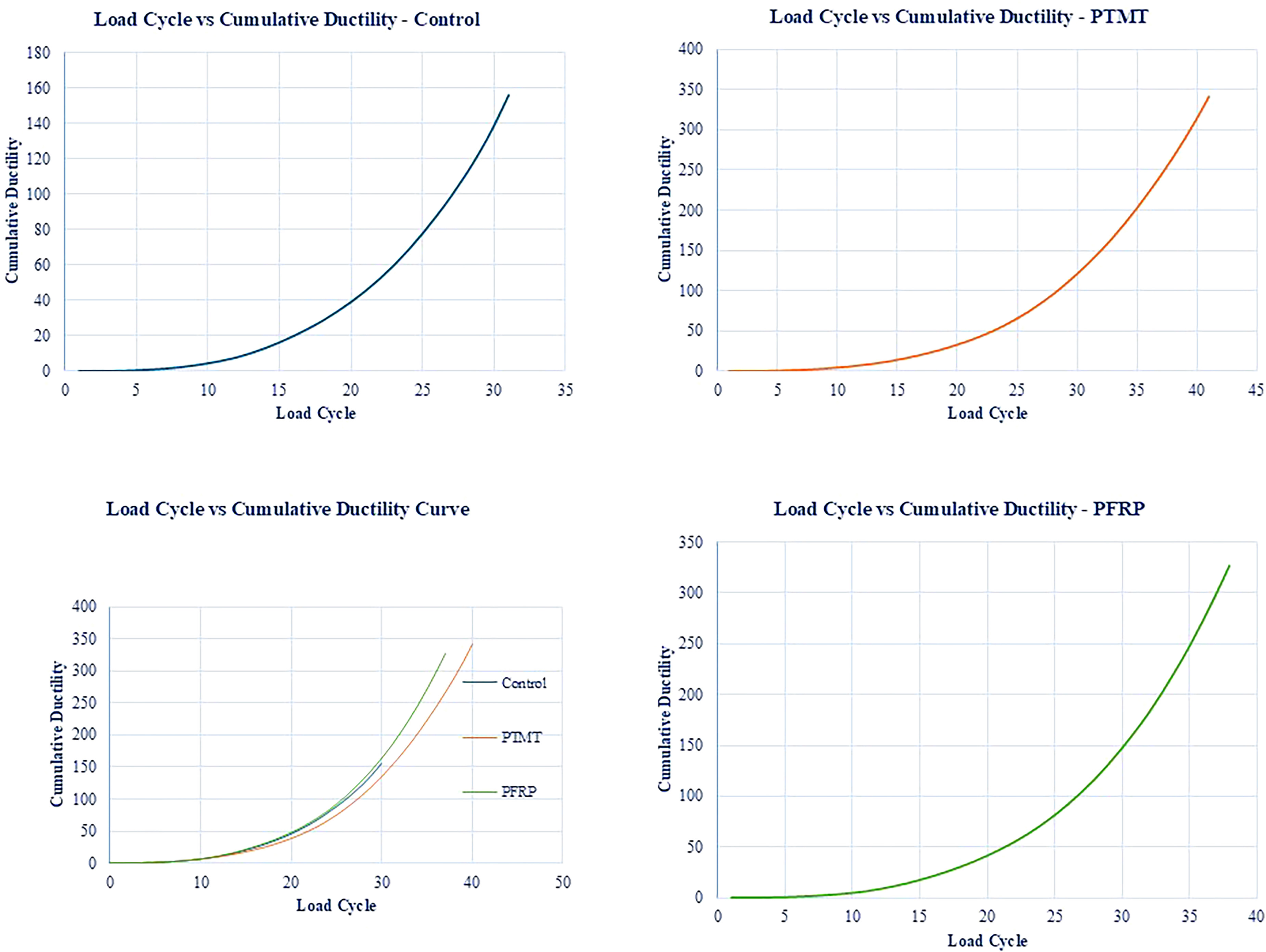
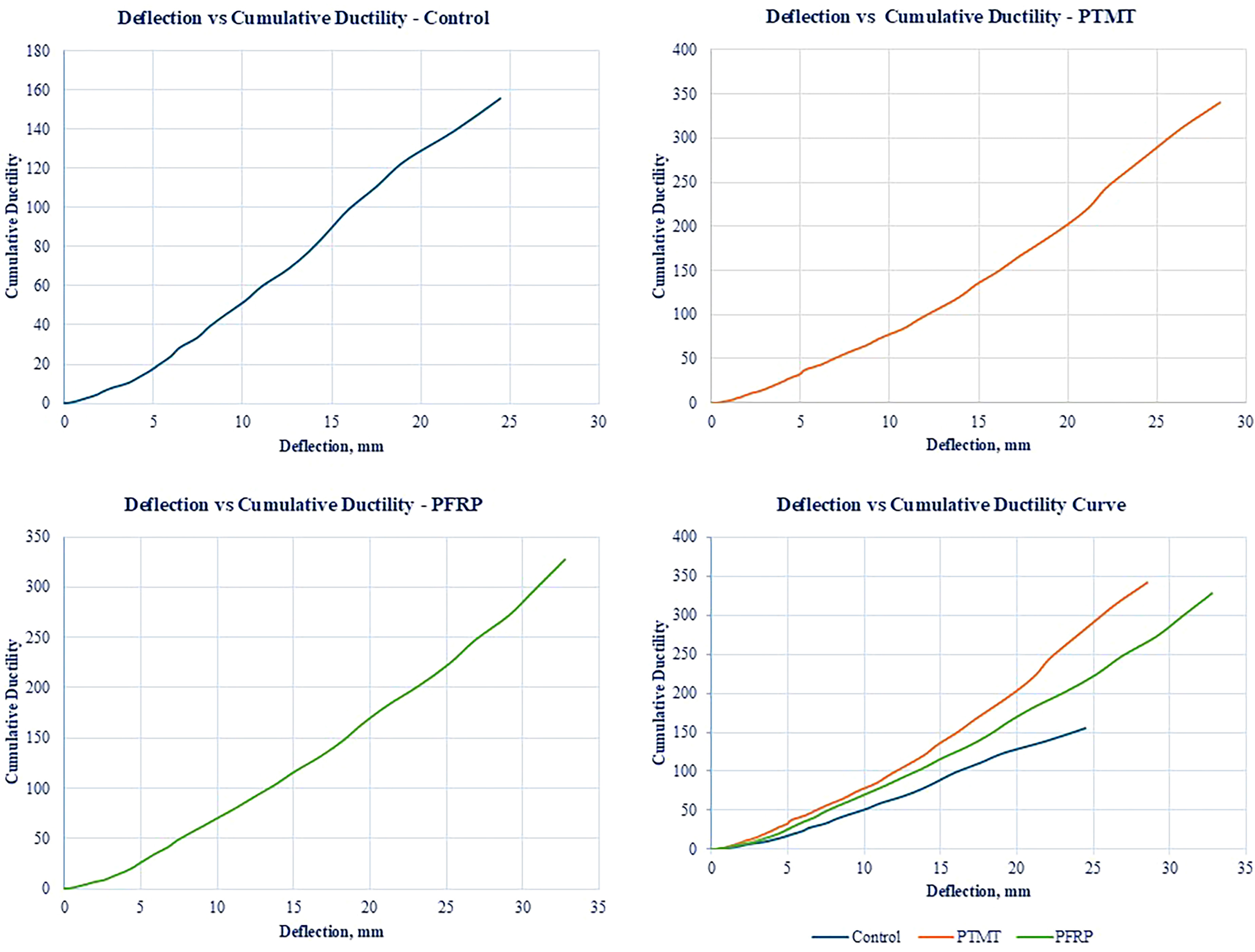
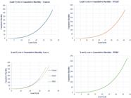
The control specimen LS1 exhibited early signs of cracking and experienced brittle-type failure after reaching peak load, with visible crushing in the concrete and widening of cracks indicating loss of load-carrying capacity. In contrast, LS2 with the PMC link slab demonstrated improved ductility, showing smaller crack widths and a more distributed cracking pattern. The material’s polymer modification contributed to delayed crack initiation and allowed the specimen to sustain greater deflections before failure. The behaviour was more gradual, suggesting improved energy dissipation. The LS3 specimen, reinforced with GFRP in the link slab, displayed the highest ductility among the three. The use of GFRP contributed to enhanced post-cracking performance, reduced crack propagation, and increased strain capacity. The failure mode was more ductile, with significant deflection observed before failure occurred.
As per the result, if the deflection increases the cumulative ductility of the specimen LS1, LS2 and LS3 is increased gradually. Among the specimens, LS3 exhibited the highest ductility performance, with a maximum deflection of 32.8 and a cumulative ductility value of 327.29. The graph plotting the ductility is shown in Figures 14, 15 and 16.

4.7. Stress–strain behaviour of slabs
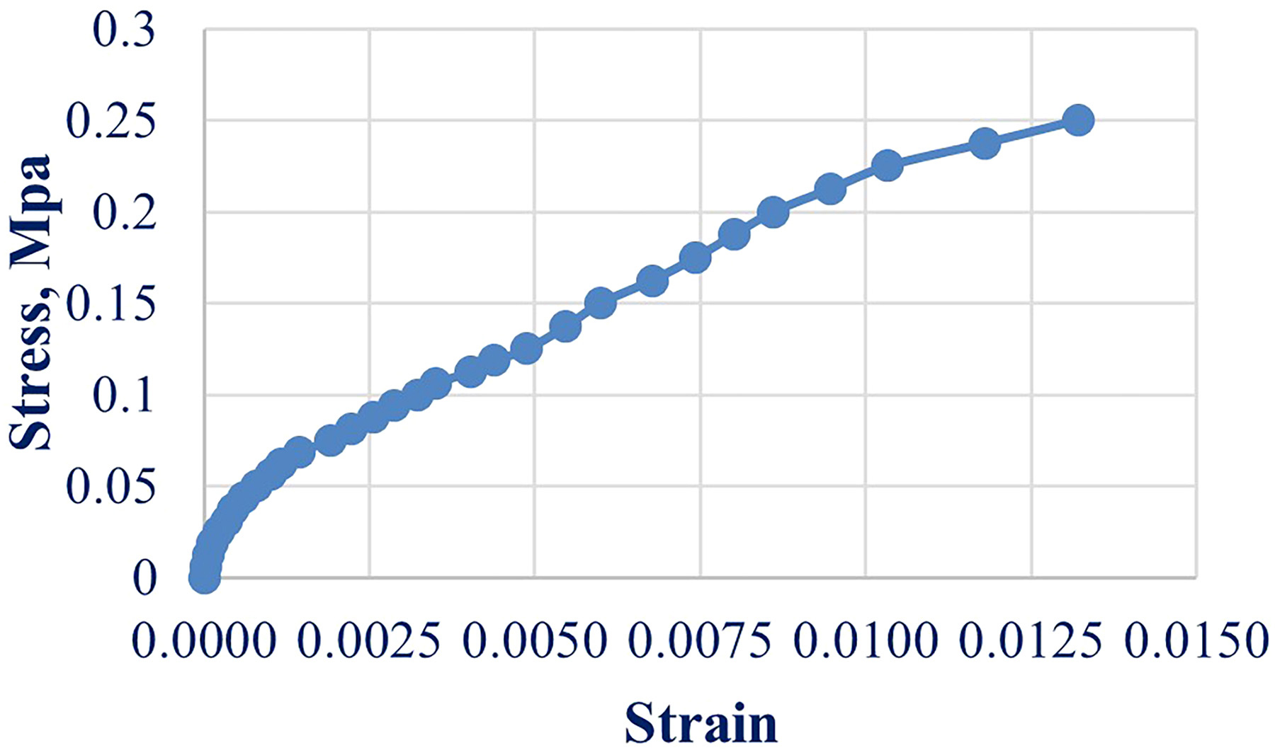
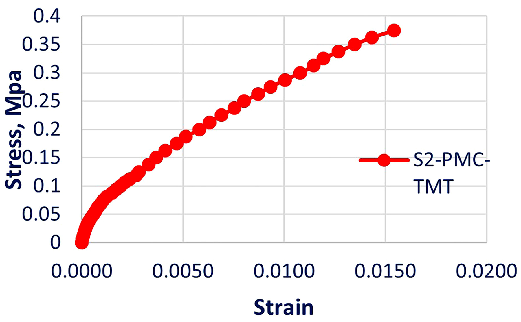
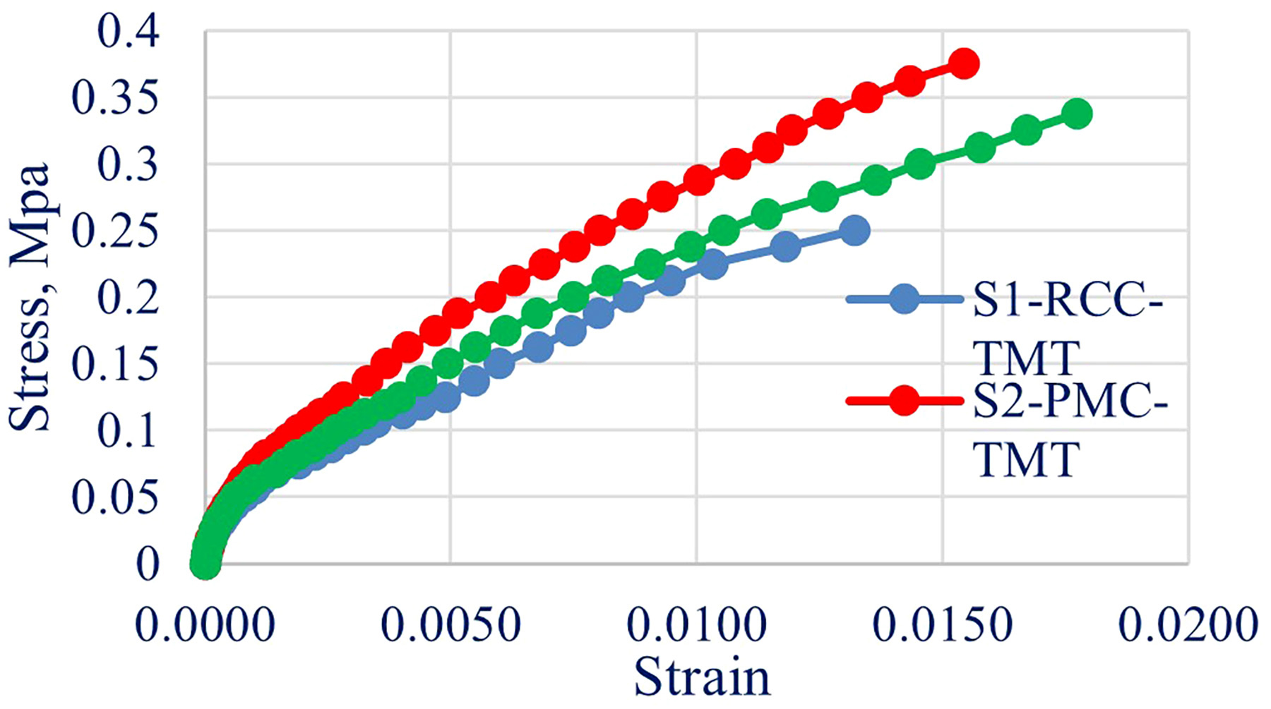
In this experimental program, strain gauges were not installed on the reinforcement due to the limited cross-sectional depth of the 1/4-scale specimens and the possibility of premature gauge detachment during cyclic loading. Instead, load–deflection data and observed cracking patterns were used to infer the stress–strain response and the contribution of the reinforcement. This indirect approach is consistent with the methodology adopted by [10, 11], where flexural behaviour and ductility indices were derived from global mid-span deflection rather than internal strain readings. The stress strain characteristics of the three specimen are presented in the Figures 17, 18, 19 and 20 exhibited the the distinct mechanical responses under flexural loading. During the initial stage of loading, all three specimen exhibited the linear response between the stress and strain that signifies the elastic behaviour and the efficient stress transfer within the concrete matrix. The polymer modified specimen LS2 and LS3 shows the steeper initial slopes compared to the specimen LS1, which indicates the high modulus of elasticity and improved stiffness.
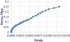
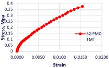
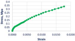
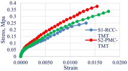
This enhancement is mainly due to the superior interfacial adhesion bond between the polymer modified matrix and the reinforcement as mentioned in the previous studies [43].
Due to progressive loading, LS2 maintained the linear behaviour over a wider strain range that implies the delayed crack initiation and better stress redistribution. The addition of acrylic polymer in the concrete improves the cohesion and reduces the micro crack formation which results in a smoother crack propagation and enhanced post yield performance. Simultaneously, LS3 exhibited the highest strain capacity and shows the gradual transition from elastic to plastic region without abrupt stress drops beyond the peak load. This behaviour of LS2 reflected the superior ductility, energy absorption and crack bridging effects mainly due to GFRP bars along with the flexible polymer modified concrete matrix.
Compared to the brittle failure observed in LS1, both polymer modified slabs LS2 and LS3 demonstrated ductile post peak behaviour while LS3 showing the most resilient and durable response. The results confirms that the combined use of polymer modified concrete and GFRP reinforcement significantly enhances toughness, flexural stiffness and long-term structural performance, particularly under sustained or cyclic loading conditions.
4.8. Discussion on energy absorption capacity
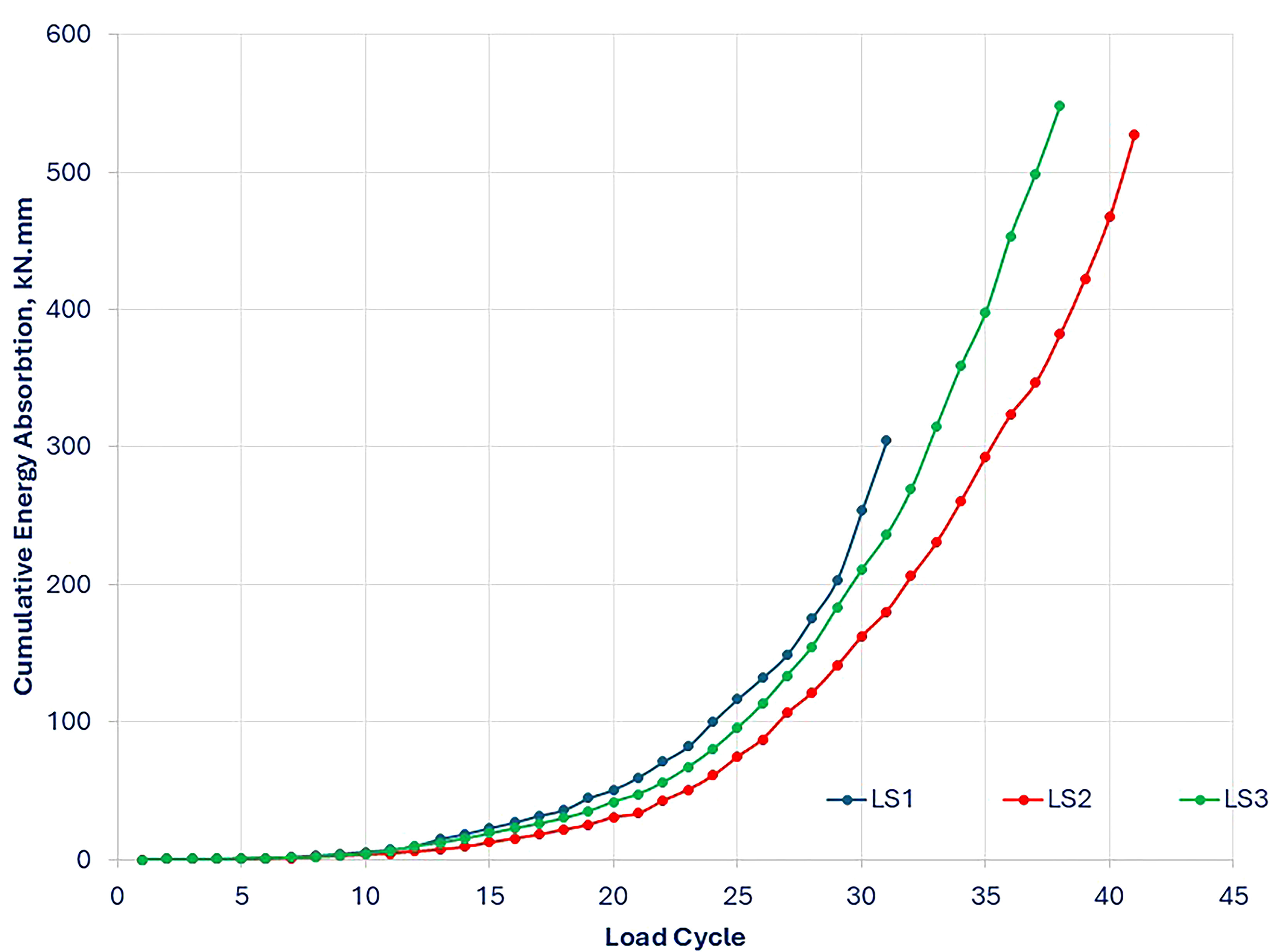
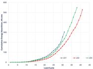
The cumulative Energy absorption capacity results obtained from the three specimen LS1, LS2 ans LS3 shows the clear performance defection. The cumulative energy absorption reaches for LS1 is 304.70 kN mm and this this value represent the least energy dissipation capacity compared to other specimen. The LS1 specimen shows the lowest capacity and its response rises slowly in the early cycles before increases more sharply near failure. This condition shows the brittle nature of the specimen where stiffness reduces once the cracking appear in the specimen which leads to limited deformation toleranxe and early loss of resistance.
A significant improvement is observed in the specimen LS2 and its cumulative energy absorption reaches 527.48 kN mm. The steady increases of this value during the loading cycle reflects the improved ductility behaviour and load carrying capacity. When the loading further increases, the behaviour of Polymer matrix causes the specimen to exhibit much better ductility and more stable load carrying capacity behaviour. The polymer matrix formation in the polymer modified concrete strengthen the bond of the composite and delays the crack initiation and improves the slab behaviour to be more stiff. As a result, the specimen LS2 exhibits the uniform distribution of stresses and a considerably enhanced capacity to resist the loading.
The LS3 specimen exhibits the value of 560 kN mm of highest cumulative energy absorption capacity among the three specimen as shown in Figure 21. Compared to LS1 and LS2, the LS3 exhibited the smooth increases of energy absorption throughout the entire loading cycle. This constant and gradual increase the ability of LS3 to dissipate energy and having deformation without sudden loss of stiffness or sudden crack. The combined effect of Polymer modified concrete and GFRP reinforcement enhance the slab flexibility and stabilizes the distribution of stress during the repeated loading. this allows LS3 to attain greater deflection without the affecting the structural integrity. The LS3 exhibits the greater ductile behaviour and the resistance to cyclic deformation.
4.9. Crack propagation behaviour
The crack development in the three specimen were monitored and recorded visually during the loading process. The crack width were pointed and measured by using scaled marking placed on the specimen surface and verified by using the graduated scale rule at each loading incremental stages. Measurement were taken at several point where the cracks appear during the loading cycle that is near midspan and support zone to track the progress and pattern of cracks. The crack development and its width were recorded and marked by two observer and the average values were considered to reduces the subjective error as mentioned in past research findings [10, 11]. The progress of crack formation of three specimen LS1, LS2 and LS3 were recorded to find the behaviour of different material and reinforcement types to reduce the crack formation and micro cracks.
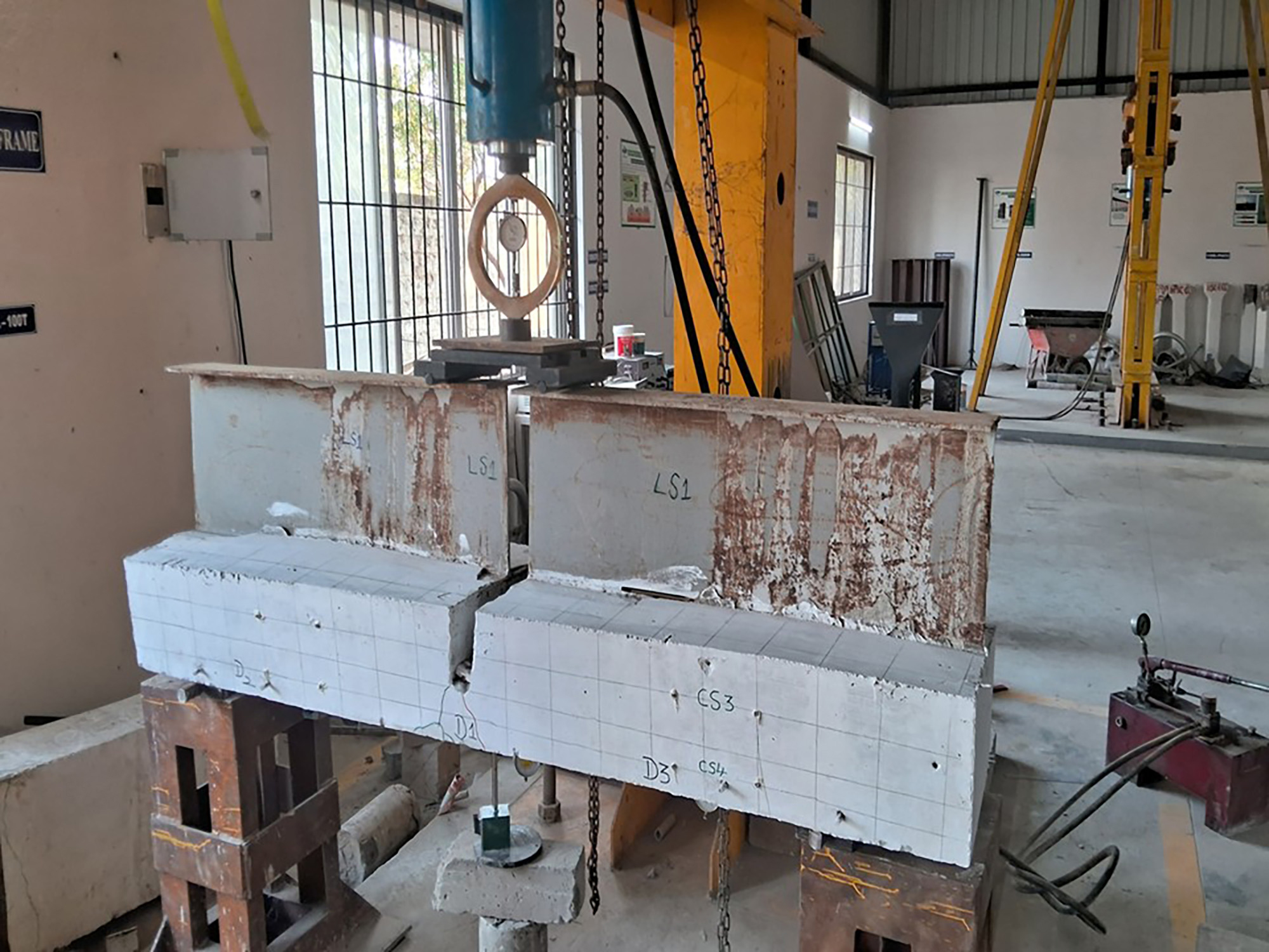
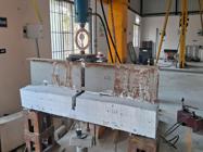
The specimen LS1 shows the early formation of cracks appears at the midspan and the surface of the slab, the initial crack appear at the load level of 3.0 kN. As the loading increases, the cracks at the mid span widen and spread throughout the length of the specimen towards the compression zone. The micro cracks appeared at the length of the specimen during the increase of load which leads to brittle failure. The first cracks of 3 mm width were appeared at the load of 3.0 kN with 0.82 mm deflection and also fewer appeared in the central region of link slabs.
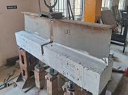
The Specimen LS2 exhibited the denser formation of finer crack which is at the load of 3.5 kN with a deflection of 0.84 mm. The crack pattern was more gradual and distributed across the length of the link slab, mainly in the debonded region. The polymer modified concrete improves the crack bridging capacity of the specimen and reduces the crack width and improve its durability capacity.
The specimen LS3 exhibited the significant crack propagation behaviour. The initial cracks are appeared at the load of 4.0 kN with the deflection of 1.16 mm. this shows the combined effect of the polymer modified concrete and GFRP reinforcement which facilitates the fine multi crack pattern that evenly spreads across the slab without the localized damage. The value of final crack width remains under 0.1 mm with no major spalling or crushing observed in the specimen during testing. This suggests that the specimen LS3 shows the greater structural integrity and damage tolerance throughout the loading. The crack behaviour for the specimen LS1, LS2 and LS3 is presented in the Figures 22, 23 and 24 and Table 5.

5. CONCLUSION
Based on the experimental investigations on polymer-modified concrete (PMC) with GFRP reinforcement, the optimum polymer content was identified as 15%, providing the most balanced enhancement in strength and performance characteristics.
-
The compressive strength reached approximately 45–46 MPa at 15% polymer content, showing improved matrix densification and better load-bearing efficiency compared to the control mix.
-
The tensile strength also peaked at around 7.3–7.5 MPa, highlighting superior microcrack bridging, enhanced interfacial bonding, and increased overall ductility.
-
The flexural strength exhibited nearly a 50% increase over the control mix, confirming improved crack resistance, energy absorption, and bending behaviour of the polymer-modified composite.
-
The experimental findings confirm that link slabs constructed with PMC and FRP reinforcement (LS3) are more effective in enhancing the flexural performance and serviceability of jointless bridge decks.
-
These results validate the potential of such configurations in extending the functional lifespan of bridge systems while mitigating maintenance challenges associated with traditional expansion joints.
-
The results confirm that replacing traditional RCC link slabs with PMC and GFRP reinforcement significantly enhances the structural performance and serviceability of bridge decks. The deflection profiles indicate that such link slab systems are well-suited for jointless bridge applications requiring high deformation tolerance and durability.
-
The improved performance of LS3 can be attributed to the enhanced synergy between the tensile properties of GFRP and the strain compatibility provided by the PMC matrix. LS2 also showed satisfactory degradation control, making it a viable alternative to conventional RCC systems.
-
The use of PMC and GFRP reinforcement significantly mitigates stiffness degradation, enhances crack resistance, and improves the long-term structural behaviour of bridge deck link slabs under repeated loading.
-
The use of polymer-modified concrete (LS2 and LS3) significantly delayed crack initiation and controlled crack widths, improving overall durability. GFRP reinforcement in LS3 further enhanced crack distribution and minimized crack width, demonstrating superior crack resistance and long-term structural performance.
-
The LS3-PMC-GFRP slab exhibited the highest strain capacity and maintained stress beyond the elastic limit, showing superior ductility and flexibility due to the synergistic effect of the polymer matrix and GFRP reinforcement. Unlike the brittle failure of the control specimen (LS1), both polymer-modified slabs showed ductile post-peak behaviour, with LS3-PMC-GFRP displaying the most stable and resilient stress–strain response as single point.
-
The increase in absorbed energy indicates a significant improvement in post-crack ductility and toughness, with LS2-PMC-TMT showing a ~50% increase and LS3-PMC-GFRP a 27% increase over the control.
-
LS3, enhanced with GFRP reinforcement within the PMC link slab, demonstrated the most ductile behaviour. The GFRP reinforcement contributed to higher strain tolerance, finer crack distribution, and greater energy absorption under repeated loading.
6. LIMITATION AND FUTURE WORK
-
The Future work will include additional specimens and finite element simulations using ANSYS to validate the observed load–deflection and stiffness trends. In addition, machine learning models will be developed to predict the structural performance based on polymer content and reinforcement type. This combined experimental–numerical–computational approach will enhance the reliability and scalability of PMC–GFRP link slab behaviour predictions.
-
Future studies will incorporate combined loading conditions, including fatigue, temperature gradients, and environmental exposures such as chloride attack and thermal cycling, to replicate real bridge service conditions more comprehensively. Future research will include exposure studies under chloride, temperature, and UV cycles to evaluate the long-term durability performance of PMC link slabs in real service environments.
7. BIBLIOGRAPHY
-
[1] BHARANI, S., GULSHANTAJ, M.N.A., “Seismic response of composite bridges: a review”, In: Kanwar, V.S., Sharma, S.K., Prakasam, C. (eds), Proceedings of International Conference on Innovative Technologies for Clean and Sustainable Development (ICITCSD – 2021), Cham, Springer, 2022. doi: https://doi.org/10.1007/978-3-030-93936-6_41.
» https://doi.org/10.1007/978-3-030-93936-6_41 -
[2] CANER, A., Analysis and design of jointless bridge decks supported by simple-span girders, ProQuest, 1996, https://search.proquest.com/openview/f767bee3b7522eb2732c8381f62ee3ea/1?pq-origsite=gscholar&cbl=18750&diss=y, accessed in August, 2025.
» https://search.proquest.com/openview/f767bee3b7522eb2732c8381f62ee3ea/1?pq-origsite=gscholar&cbl=18750&diss=y -
[3] CANER, A., DOGAN, E., ZIA, P., “Seismic performance of multisimple-span bridges retrofitted with link slabs”, Journal of Bridge Engineering, v. 7, n. 2, pp. 85–93, 2002. doi: https://doi.org/10.1061/(ASCE)1084-0702(2002)7:2(85).
» https://doi.org/10.1061/(ASCE)1084-0702(2002)7:2(85) -
[4] OKEIL, A.M., ELSAFTY, A., “Partial continuity in bridge girders with jointless decks”, Practice Periodical on Structural Design and Construction, v. 10, n. 4, pp. 229–238, 2005. doi: https://doi.org/10.1061/(ASCE)1084-0680(2005)10:4(229).
» https://doi.org/10.1061/(ASCE)1084-0680(2005)10:4(229) -
[5] LIU, Y., ZHANG, Q., BAO, Y., et al., “Fatigue behavior of orthotropic composite deck integrating steel and engineered cementitious composite”, Engineering Structures, v. 220, pp. 111017, 2020. doi: https://doi.org/10.1016/j.engstruct.2020.111017.
» https://doi.org/10.1016/j.engstruct.2020.111017 -
[6] AL-ROUSAN, R.Z., ALHASSAN, M., AL-WADI, R., “Nonlinear finite element analysis of full-scale concrete bridge deck slabs reinforced with FRP bars”, Structures, v. 27, pp. 1820–1831, 2020. doi: https://doi.org/10.1016/j.istruc.2020.08.024.
» https://doi.org/10.1016/j.istruc.2020.08.024 -
[7] ALROUSAN, R.Z., ALNEMRAWI, B.R., “The behavior of alkali-silica reaction-damaged full-scale concrete bridge deck slabs reinforced with CFRP bars”, Results in Engineering, v. 16, pp. 100651, 2022. doi: https://doi.org/10.1016/j.rineng.2022.100651.
» https://doi.org/10.1016/j.rineng.2022.100651 - [8] NIELSON, B.G., ASCE, M., DESROCHES, R., “Seismic performance assessment of simply supported and continuous multispan concrete girder highway bridges”, Journal of Bridge Engineering, v. 12, n. 5, pp. 611–620, 2007.
-
[9] KEOLEIAN, G.A., KENDALL, A., DETTLING, J.E., et al., “Life cycle modeling of concrete bridge design: comparison of engineered cementitious composite link slabs and conventional steel expansion joints”, Journal of Infrastructure Systems, v. 11, n. 1, pp. 51–60, 2005. doi: https://doi.org/10.1061/(ASCE)1076-0342(2005)11:1(51).
» https://doi.org/10.1061/(ASCE)1076-0342(2005)11:1(51) -
[10] LEPECH, M.D., LI, V.C., “Application of ECC for bridge deck link slab”, Materials and Structures, v. 42, n. 9, pp. 1185–1195, 2009. doi: https://doi.org/10.1617/s11527-009-9544-5.
» https://doi.org/10.1617/s11527-009-9544-5 - [11] SAHMARAN, M., LI, V., ANDRADE, C., “Corrosion resistance performance of steel-reinforced engineered cementitious composite beams”, ACI Materials Journal, v. 105, n. 3, pp. 243–250, 2008.
-
[12] LAMICHHANE, R., SHUWEN, Z., PENGFEI, Z., et al., “Stress analysis of hollow slab bridge deck pavement”, Civil and Environmental Engineering, v. 18, n. 2, pp. 589–602, 2022. doi: https://doi.org/10.2478/cee-2022-0056.
» https://doi.org/10.2478/cee-2022-0056 -
[13] FARHAN, A., DEWANGAN, U.K., “Finite element analysis of bridge deck using MATLAB”, ASPS Conference Proceedings, v. 1, pp. 1863–1870, 2022. doi: https://doi.org/10.38208/acp.v1.731.
» https://doi.org/10.38208/acp.v1.731 -
[14] GHEITASI, A., HARRIS, D.K., “Effect of deck deterioration on overall system behavior, resilience and remaining life of composite steel girder bridges”, In: Proceedings of the Structures Congress 2014, pp. 623–634, 2014. doi: https://doi.org/10.1061/9780784413357.056.
» https://doi.org/10.1061/9780784413357.056 -
[15] FANJIANG, G.N., YE, Q., FERNANDEZ, O.N., et al., “Fatigue analysis and design of steel orthotropic deck for Bronx-Whitestone Bridge, New York City”, Transportation Research Record: Journal of the Transportation Research Board, v. 1892, n. 1, pp. 69–77, 2004. doi: https://doi.org/10.3141/1892-08.
» https://doi.org/10.3141/1892-08 -
[16] KIM, Y., FISCHER, G., LI, V., Fatigue response of bridge deck link slabs designed with ductile engineered cementitious composite (ECC), University of Michigan, 2004, https://deepblue.lib.umich.edu/bitstream/handle/2027.42/84785/YunYKimAndVictorCLi.pdf?sequence=1, accessed in August, 2025.
» https://deepblue.lib.umich.edu/bitstream/handle/2027.42/84785/YunYKimAndVictorCLi.pdf?sequence=1 -
[17] KHITAB, A., NADEEM, M., HUSSAIN, S., “Use of flexible engineered cementitious composite in building”, Key Engineering Materials, v. 510–511, pp. 591–596, 2012. doi: https://doi.org/10.4028/www.scientific.net/KEM.510-511.591.
» https://doi.org/10.4028/www.scientific.net/KEM.510-511.591 -
[18] CHU, K., HOSSAIN, K.M.A., LACHEMI, M., “Fatigue behaviour of joint-free bridges with steel and GFRP-reinforced ECC link slabs”, Structures, v. 47, pp. 829–845, 2023. doi: https://doi.org/10.1016/j.istruc.2022.11.093.
» https://doi.org/10.1016/j.istruc.2022.11.093 -
[19] KARIM, R., SHAFEI, B., “Performance of fiber-reinforced concrete link slabs with embedded steel and GFRP rebars”, Engineering Structures, v. 229, pp. 111590, 2021. doi: https://doi.org/10.1016/j.engstruct.2020.111590.
» https://doi.org/10.1016/j.engstruct.2020.111590 -
[20] KRISHNAMOORTHY, S.K., SUBBAIYAN, A., SUBRAMANIAM, N.K., et al., “Enhancing flexural capacity and crack resistance of two-span continuous beams with engineered cementitious composite (ECC) under static loading conditions”, Matéria, v. 30, e20240671, 2025. doi: https://doi.org/10.1590/1517-7076-rmat-2024-0671.
» https://doi.org/10.1590/1517-7076-rmat-2024-0671 -
[21] LEPECH, M.D., “Sustainable infrastructure systems using engineered cementitious composites”, In: Proceedings of the Structures Congress 2009: Don’t Mess with Structural Engineers: Expanding Our Role, pp. 2232–2241, 2009. doi: https://doi.org/10.1061/41031(341)244.
» https://doi.org/10.1061/41031(341)244 -
[22] OZYILDIRIM, H., VIEIRA, M., Exploratory investigation of high-performance fiber-reinforced cementitious composites for crack control Virginia Transportation Research Council, 2008, https://rosap.ntl.bts.gov/view/dot/20106 (accessed August 12, 2025).
» https://rosap.ntl.bts.gov/view/dot/20106 - [23] LEPECH, M., LI, V., ROBERTSON, R.E., et al., “Design of green engineered cementitious composites for improved sustainability”, ACI Materials Journal, v. 105, pp. 567, 2008, https://www.academia.edu/download/87075382/bddd1bc113f2ebc34140b4023b16d18b37da.pdf, accessed in August, 2025.
-
[24] HOU, M., HU, K., YU, J., et al., “Experimental study on ultra-high ductility cementitious composites applied to link slabs for jointless bridge decks”, Composite Structures, v. 204, pp. 167–177, 2018. doi: https://doi.org/10.1016/j.compstruct.2018.07.067.
» https://doi.org/10.1016/j.compstruct.2018.07.067 -
[25] EL-SAFTY, A., “Extending the service life of bridges using CFRP laminates and continuous decks”, In: Proceedings of the Structures Congress 2008: Crossing Borders, pp. 1–10, 2008. doi: https://doi.org/10.1061/41016(314)23.
» https://doi.org/10.1061/41016(314)23 -
[26] SABER, A., ALETI, A.R., “Behavior of FRP link slabs in jointless bridge decks”, Advances in Civil Engineering, v. 2012, pp. 1–9, 2012. doi: https://doi.org/10.1155/2012/452987.
» https://doi.org/10.1155/2012/452987 -
[27] SPAGNUOLO, S., RINALDI, Z., DONNINI, J., et al., “Physical, mechanical and durability properties of GFRP bars with modified acrylic resin (modar) matrix”, Composite Structures, v. 262, pp. 113557, 2021. doi: https://doi.org/10.1016/j.compstruct.2021.113557.
» https://doi.org/10.1016/j.compstruct.2021.113557 -
[28] BOOPAPHI, R.S.J., DASNAMOORTHY, R., CHANDRASEKARAN, M.K., et al., “Study on polymeric coatings on fly ash concrete under seawater”, Environmental Science and Pollution Research International, v. 28, n. 8, pp. 9338–9345, 2021. doi: https://doi.org/10.1007/s11356-020-11451-2. PubMed PMID: 33141383.
» https://doi.org/10.1007/s11356-020-11451-2 -
[29] XIN, H., MOSALLAM, A., LIU, Y., et al., “Experimental and numerical investigation on in-plane compression and shear performance of a pultruded GFRP composite bridge deck”, Composite Structures, v. 180, pp. 914–932, 2017. doi: https://doi.org/10.1016/j.compstruct.2017.08.066.
» https://doi.org/10.1016/j.compstruct.2017.08.066 -
[30] VISWANATHAN, K.E., KRISHNARAJA, A.R., SUBRAMANIAM, A., et al., “Flexural performance of reinforced concrete beam with layer of hybrid strain-hardening cementitious composites”, Matéria, v. 30, , 2025. doi: https://doi.org/10.1590/1517-7076-rmat-2024-0697.
» https://doi.org/10.1590/1517-7076-rmat-2024-0697 -
[31] AYYADURAI, A., MUTHUCHAMY, S.M., DHANASEKARAN, M., et al., “Predictive experimental and mathematical insights into integrating nano-additives and basalt fibre in high-strength concrete beams”, Matéria, v. 30, , 2025. doi: https://doi.org/10.1590/1517-7076-rmat-2025-0465.
» https://doi.org/10.1590/1517-7076-rmat-2025-0465 -
[32] BEDI, R., CHANDRA, R., SINGH, S.P., “Mechanical properties of polymer concrete”, Journal of Composites, v. 20, pp. 948745, 2013. doi: https://doi.org/10.1155/2013/948745.
» https://doi.org/10.1155/2013/948745 -
[33] BHARANI, S., KUMAR, G.R., SURYAVARMAN, R., “An investigation on properties of polymer modified concrete and its application: a review”, AIP Conference Proceedings, v. 3267, pp. 020094, 2025. doi: https://doi.org/10.1063/5.0265788.
» https://doi.org/10.1063/5.0265788 -
[34] KNAPEN, E., VAN GEMERT, D., “Cement hydration and microstructure formation in the presence of water-soluble polymers”, Cement and Concrete Research, v. 39, n. 1, pp. 6–13, 2009. doi: https://doi.org/10.1016/j.cemconres.2008.10.003.
» https://doi.org/10.1016/j.cemconres.2008.10.003 -
[35] SANAEI ATAABADI, H., ZARE, A., RAHMANI, H., et al., “Lightweight dense polymer concrete exposed to chemical condition and various temperatures: an experimental investigation”, Journal of Building Engineering, v. 34, pp. 101878, 2021. doi: https://doi.org/10.1016/j.jobe.2020.101878.
» https://doi.org/10.1016/j.jobe.2020.101878 -
[36] TAYEH, B.A., ABU BAKAR, B.H., MEGAT JOHARI, M.A., et al., “Evaluation of bond strength between normal concrete substrate and ultra high performance fiber concrete as a repair material”, Procedia Engineering, v. 54, pp. 554–563, 2013. doi: https://doi.org/10.1016/j.proeng.2013.03.050.
» https://doi.org/10.1016/j.proeng.2013.03.050 -
[37] TAYEH, B.A., ABU BAKAR, B.H., MEGAT JOHARI, M.A., et al., “Mechanical and permeability properties of the interface between normal concrete substrate and ultra high performance fiber concrete overlay”, Construction & Building Materials, v. 36, pp. 538–548, 2012. doi: https://doi.org/10.1016/j.conbuildmat.2012.06.013.
» https://doi.org/10.1016/j.conbuildmat.2012.06.013 -
[38] LAMPROPOULOS, A.P., PASCHALIS, S.A., TSIOULOU, O.T., et al., “Strengthening of reinforced concrete beams using ultra high performance fibre reinforced concrete (UHPFRC)”, Engineering Structures, v. 106, pp. 370–384, 2016. doi: https://doi.org/10.1016/j.engstruct.2015.10.042.
» https://doi.org/10.1016/j.engstruct.2015.10.042 -
[39] ULKU, E., ATTANAYAKE, U., AKTAN, H., “Jointless bridge deck with link slabs: design for durability”, Transportation Research Record: Journal of the Transportation Research Board, v. 2131, n. 1, pp. 68–78, 2009. doi: https://doi.org/10.3141/2131-07.
» https://doi.org/10.3141/2131-07 - [40] JOSE, T., JOLLY, E., STANLY, E., et al., “Structural analysis and reinforcement design of a simply supported Bridge at Edayar using CSiBridge software”, International Research Journal of Engineering and Technology, v. 8, n. 9, pp. 1400–1404, 2021.
-
[41] GERGESS, A.N., HAWI, P.F., “Structural behavior of debonded link-slabs in continuous bridge decks”, Journal of Bridge Engineering, v. 24, n. 5, pp. 04019030, 2019. doi: https://doi.org/10.1061/(ASCE)BE.1943-5592.0001388.
» https://doi.org/10.1061/(ASCE)BE.1943-5592.0001388 -
[42] MOSTAFA, A., RADWAN, L., GADELLAH, A., et al., “Behavior of link slab bridge girders with jointless deck”, International Journal of Bridge Engineering, v. 8, n. 2, pp. 1–24, 2020, https://www.researchgate.net/profile/Ahmed-Elmannaey/publication/376991134_BEHAVIOR_OF_LINK_SLAB_BRIDGE_GIRDERS_WITH_JOINTLESS_DECK/links/659146b82468df72d3ec1708/BEHAVIOR-OF-LINK-SLAB-BRIDGE-GIRDERS-WITH-JOINTLESS-DECK.pdf, accessed in August, 2025.
» https://www.researchgate.net/profile/Ahmed-Elmannaey/publication/376991134_BEHAVIOR_OF_LINK_SLAB_BRIDGE_GIRDERS_WITH_JOINTLESS_DECK/links/659146b82468df72d3ec1708/BEHAVIOR-OF-LINK-SLAB-BRIDGE-GIRDERS-WITH-JOINTLESS-DECK.pdf -
[43] ZHANG, L., ZHENG, Y., YU, Y., et al., “Structural performance evaluation of ECC link slabs reinforced with FRP bars for jointless bridge decks”, Construction & Building Materials, v. 304, pp. 124462, 2021. doi: https://doi.org/10.1016/j.conbuildmat.2021.124462.
» https://doi.org/10.1016/j.conbuildmat.2021.124462 -
[44] AU, A., LAM, C., AU, J., et al., “Eliminating deck joints using debonded link slabs: research and field tests in Ontario”, Journal of Bridge Engineering, v. 18, n. 8, pp. 768–778, 2013. doi: https://doi.org/10.1061/(ASCE)BE.1943-5592.0000417.
» https://doi.org/10.1061/(ASCE)BE.1943-5592.0000417 -
[45] ZHONG, J., SHEN, J., WANG, W., et al., “Working state of ECC link slabs used in continuous bridge decks”, Applied Sciences, v. 9, n. 21, pp. 4667, 2019. doi: https://doi.org/10.3390/app9214667.
» https://doi.org/10.3390/app9214667 -
[46] YOUSEFI, M., GHALEHNOVI, M., YOUSEFI, M., et al., “Steel and composite structures”, Steel and Composite Structures, v. 27, pp. 123, 2018. doi: https://doi.org/10.12989/SCS.2018.27.1.123.
» https://doi.org/10.12989/SCS.2018.27.1.123 -
[47] WANG, C., SHEN, Y., ZOU, Y., et al., “Analysis of mechanical characteristics of steel-concrete composite flat link slab on simply-supported beam bridge”, KSCE Journal of Civil Engineering, v. 23, n. 8, pp. 3571–3580, 2019. doi: https://doi.org/10.1007/s12205-019-1921-1.
» https://doi.org/10.1007/s12205-019-1921-1 -
[48] ZHENG, X., ZHANG, J., “Finite element simulation for bending behavior of steel-ECC composite slab considering shrinkage, creep and cracking”, Construction & Building Materials, v. 282, pp. 122643, 2021. doi: https://doi.org/10.1016/j.conbuildmat.2021.122643.
» https://doi.org/10.1016/j.conbuildmat.2021.122643 -
[49] ZHAO, X., XIANG, W., YANG, Y., et al., “Flexural behavior of prefabricated RC bridge deck with different joint materials”, Buildings, v. 13, n. 6, pp. 1420, 2023. doi: https://doi.org/10.3390/buildings13061420.
» https://doi.org/10.3390/buildings13061420 -
[50] MAKHLOUF, M.H., EL-AZAB, I.A., MANSOUR, M.H., “Flexural improvement of RC slabs by FRP or steel using different strengthening systems and novel anchoring techniques”, International Journal of Concrete Structures and Materials, v. 18, n. 1, pp. 45, 2024. doi: https://doi.org/10.1186/s40069-024-00683-y.
» https://doi.org/10.1186/s40069-024-00683-y -
[51] YOO, D.Y., YOON, Y.S., “Structural performance of ultra-high-performance concrete beams with different steel fibers”, Engineering Structures, v. 102, pp. 409–423, 2015. doi: https://doi.org/10.1016/j.engstruct.2015.08.029.
» https://doi.org/10.1016/j.engstruct.2015.08.029 -
[52] LUO, J., SHAO, X., FAN, W., et al., “Flexural cracking behavior and crack width predictions of composite (steel + UHPC) lightweight deck system”, Engineering Structures, v. 194, pp. 120–137, 2019. doi: https://doi.org/10.1016/j.engstruct.2019.05.018.
» https://doi.org/10.1016/j.engstruct.2019.05.018 -
[53] PHARAND, M., CHARRON, J.-P., “Experimental investigation of the shear resistance mechanism on Hybrid NSC-UHPC predamaged and undamaged unidirectional bridge slabs”, Journal of Structural Engineering, v. 149, n. 9, pp. 04023128, 2023. doi: https://doi.org/10.1061/JSENDH.STENG-12162.
» https://doi.org/10.1061/JSENDH.STENG-12162 -
[54] JIANG, H., MEI, G., SHEN, R., et al., “Experimental study and theoretical analysis on the flexural behaviors of UHPC-strengthened NC overlay in bridge deck”, Case Stud. Constr. Mater, v. 22, pp. e04187, 2025. doi: https://doi.org/10.1016/j.cscm.2024.e04187.
» https://doi.org/10.1016/j.cscm.2024.e04187 -
[55] BROQUET, C., BAILEY, S.F., FAFARD, M., et al., “Dynamic behavior of deck slabs of concrete road bridges”, Journal of Bridge Engineering, v. 9, n. 2, pp. 137–146, 2004. doi: https://doi.org/10.1061/(ASCE)1084-0702(2004)9:2(137).
» https://doi.org/10.1061/(ASCE)1084-0702(2004)9:2(137)