 Analysis of guide vane compatibility after runner replacement based on CFD
ABSTRACT
The modernization of aging hydropower infrastructure is critical for enhancing energy efficiency and extending the operational lifespan of existing stations. Against this background, the objective of this study was to optimize the geometric design of the adjustable guide vanes in the retrofit scheme of Huilong Hydropower Station by employing computational fluid dynamics (CFD) analysis of the flow passage. The aim was to reduce flow resistance and energy loss, thereby improving the hydraulic efficiency and operational stability of the turbine unit. Based on rated operating conditions, CFD simulations were carried out to compare the flow fields of the original unit and the modified unit after runner replacement. The simulation results indicate that adopting the optimized guide vanes increases the hydraulic efficiency by 0.3% (from 92.2% to 92.5%) and the power output by 206 kW (from 38,660 kW to 38,866 kW). These quantitative comparisons verify that the retrofit exerts a positive but limited influence on performance, confirming that the original guide vane design remains highly compatible with the replaced runner. This study not only refines the retrofit scheme of Huilong Hydropower Station but also provides valuable theoretical guidance and engineering references for the upgrading and optimization of similar turbine units.
Keywords:
Hydraulic Turbine Upgrading; CFD Flow Passage Analysis; Adjustable Guide Vanes; Retrofit Optimization
1. INTRODUCTION
Huilong Hydropower Station is located in the southwest of Hengren County, Liaoning Province, in the middle and lower reaches of the Hunjiang River. As the second hydropower station in the cascade development of water resources along the Hunjiang River, it is equipped with two hydraulic turbine units of model HL-702-LJ-410. As an important tributary of the Yalu River, the Hunjiang River provides stable and abundant water resources, offering excellent conditions for hydropower generation and ensuring the long-term efficient operation of the station. In addition to power generation, the station also serves functions such as irrigation and flood control, playing a vital role in promoting regional economic development and maintaining ecological balance. Since its commissioning, the flow passage components have suffered from severe degradation. Specifically, significant cavitation pitting and cracks were observed on the adjustable guide vanes and the head cover. The airfoil profile of the guide vanes has undergone serious deformation, and the guide vane bushings and sleeves are severely worn, leading to excessive leakage. Furthermore, the unreasonable design of the control mechanism has frequently caused the shear pins to break, resulting in guide vane reversal, which severely threatens the safe and stable operation of the unit. Therefore, a comprehensive retrofit of the original turbine-generator units is required.
Research on turbine optimization abroad began relatively early, with major focuses on improving numerical simulation accuracy, flow field optimization strategies, enhancement of erosion resistance, and the application of intelligent optimization algorithms. NIKOLIĆ et al. [1] highlighted the importance of infrastructure retrofitting by investigating the settling basins of small hydropower plants. MICHEL et al. [2] investigated overall retrofit schemes and proposed several renovation strategies aimed at improving the energy efficiency of aging hydropower stations. KUMARI et al. [3] reviewed the future prospects of variable-speed hydropower, emphasizing its flexibility compared to traditional units. WU et al. [4] discussed the application of CFD in turbine design optimization, emphasizing its advantages in evaluating hydrodynamic performance and optimizing blade geometry. SEMENOVA et al. [5] applied a multi-objective optimization method to the design of Kaplan turbine runner blades and achieved improvements in overall efficiency under various operating conditions. Recent international studies have further focused on guide vane geometric refinement and erosion prediction. MÜLLER et al. [6] focused on flow instabilities related to the runner crown geometry. OHIEMI et al. [7] combined inverse design methodology with CFD to optimize the guide vane geometries of a legacy Francis turbine, achieving a 9.3% reduction in profile loss and a significant decrease in secondary flow factors. Addressing erosion in sediment-laden flows, SHRESTHA et al. [8] evaluated different erosion models and found that accurate CFD simulations can effectively predict specific wear locations on guide vanes, providing a theoretical basis for durability-oriented design.In recent years, extensive CFD-based turbine optimization studies have also been conducted in China, mainly focusing on the retrofitting of small hydropower stations, guide vane optimization, and engineering applications. LAI et al. [9] proposed a numerical-experiment-based approach for turbine retrofitting, highlighting the importance of CFD in engineering decision-making. Similarly, GAO et al. [10] provided experimental validation for the optimal control of variable-speed generation systems, proving their superiority. HU et al. [11] performed three-dimensional numerical simulations of runners with long and short blades, providing data support for the optimization of turbines in small hydropower stations. LI and CHANG [12] conducted CFD simulations for the Hua’an Hydropower Plant prior to retrofitting and verified the performance variations before and after the retrofit. Focusing on structural integrity, HUANG et al. [13] recently studied the modal characteristics of runners with cracked blades under fluid effects. LU et al. [14] conducted a comprehensive flow analysis of a pump-turbine under small guide vane opening conditions, identifying that the uneven pressure distribution at the leading edge is a critical factor affecting hydraulic stability, which further underscores the importance of refined flow analysis in guide vanes. These studies demonstrate that both domestic and international research on turbine optimization emphasize the use of numerical simulation technologies and innovative optimization methodologies, particularly in enhancing turbine efficiency, extending service life, and improving erosion resistance.
However, despite the extensive literature, a critical research gap remains. Most existing studies, such as those on variable-speed units or complex runner modifications, imply high investment costs or complete component replacement. There is a lack of detailed feasibility studies on minimal intervention retrofits, specifically scenarios where the runner geometry is strictly fixed due to budget constraints, and only the guide vanes can be modified to correct hydraulic mismatch. The novelty of this paper lies in addressing this specific engineering dilemma. It proposes a “Constraint-Based Inverse Design” strategy to verify whether micro-adjusting the guide vanes alone is sufficient, serving as a decision-support framework to evaluate the cost-benefit ratio of limited retrofits.
In view of the retrofit requirements of Huilong Hydropower Station, this study conducts a structural modification of the adjustable guide vanes based on CFD simulations of the flow passage. Under the premise of maintaining the runner, flow passage geometry, and rotational speed unchanged, the guide vane structures are optimized to improve the hydraulic performance of the unit. The main work of this study includes: (1) performing CFD flow field simulations of the original guide vanes to evaluate their hydraulic performance, (2) applying modern turbine design concepts to redesign and replace the optimized guide vanes, (3) conducting CFD flow field simulations of the modified unit to verify the feasibility and effectiveness of the retrofit scheme. The findings of this study provide a scientific basis for the retrofit of Huilong Hydropower Station and offer valuable references for the modernization and upgrading of similar hydropower units.
2. METHODOLOGY
2.1. Numerical model
The internal flow in the hydraulic turbine is governed by the conservation of mass and momentum. Assuming the flow is steady and incompressible, the Reynolds-Averaged Navier-Stokes (RANS) equations are solved. To close the governing equations, the Standard k – ε turbulence model is employed due to its robustness in engineering applications.
2.1.1. Governing equations
The continuity and momentum equations can be expressed in tensor notation as follows:
where ρ is the fluid density, ui represents the time-averaged velocity components, p is the pressure, and µ is the dynamic viscosity. The term represents the Reynolds stresses.
2.1.2. Turbulence closure
To close the governing equations, the Reynolds stresses are modeled using the Boussinesq hypothesis:
The eddy viscosity µt is computed using the standard k – ε turbulence model. The transport equations for the turbulent kinetic energy (k) and the turbulent dissipation rate (ε) are given by:
where Gk represents the generation of turbulence kinetic energy due to mean velocity gradients. The standard model constants are C1ε = 1.44,C2ε = 1.92,σk = 1.0 and σε = 1.3.
2.2. Performance evaluation indicators
To quantify the hydraulic performance, the turbine output and efficiency are calculated based on the simulated flow field. The turbine output is calculated as:
where Pout represents the power output (W), is the driving torque of water flow to the runner (N · m), and ω is the rotating angular velocity of the runner (). The working head (H) is obtained by calculating the energy difference between the turbine inlet section and the draft tube outlet section:
where p represents the static pressure value of the inlet and outlet surface of the turbine (Pa), Z is the elevation of grid points (m), V is the absolute velocity value on this surface (m/s), ρ is the fluid density (kg/m3), N is the number of grid points on this surface, and g is the gravity acceleration (m/s2).
The hydraulic efficiency calculation formula of the turbine is as follows:
where Q is the flow rate () and H is the effective head calculated above.
2.3. Operating conditions
The simulation and optimization are conducted under the rated operating point of the Huilong Hydropower Station. The key dimensionless parameters, unit speed (n11) and unit discharge (Q11), are calculated as follows:
The numerical simulations and optimization processes are conducted under the specific rated operating conditions of the Huilong Hydropower Station, characterized by a rated head (H) of 28 m, a rated discharge (Q) of 153 m3/s, and a runner diameter (D1) of 4.5 m. These parameters serve as the consistent baseline for all subsequent comparative analyses between the original and modified guide vane designs.
3. NUMERICAL SIMULATION SETUP AND GUIDE VANE MODIFICATION SCHEME
3.1. Computational model and mesh generation
3.1.1. Geometric modeling
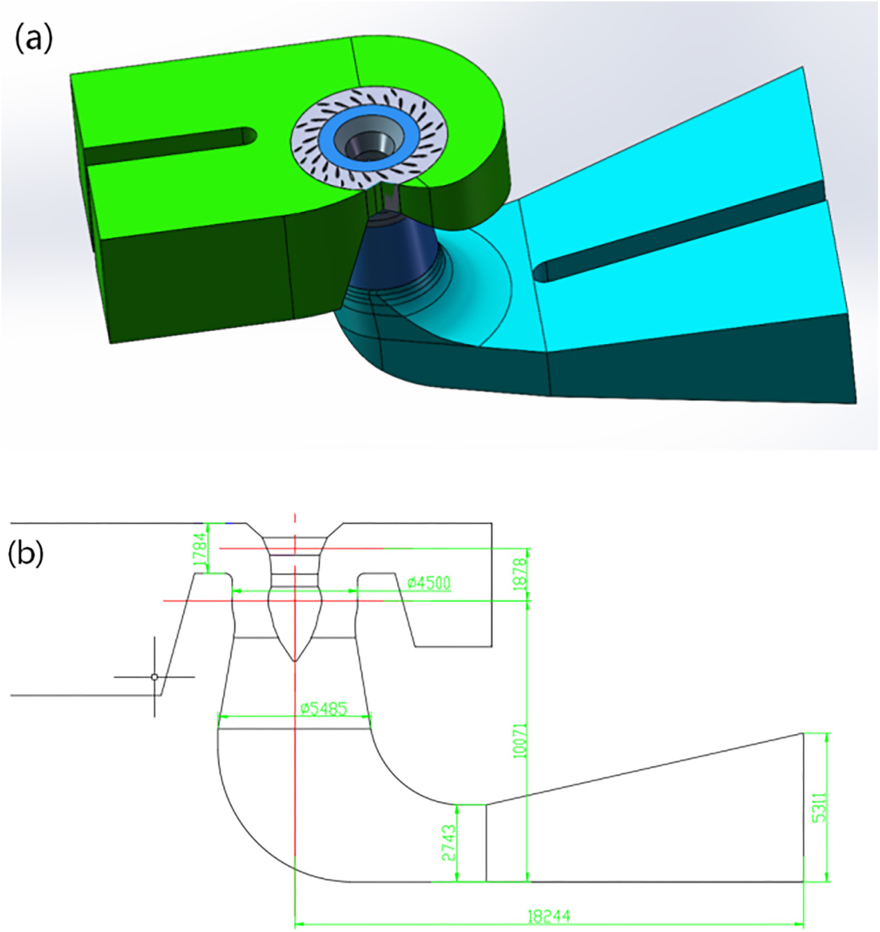
The three-dimensional model of the flow passage of the original hydraulic turbine under rated conditions was established using SOLIDWORKS. A split-assembly modeling approach was adopted [15]. In this method, the entire computational flow passage of the turbine is divided into four parts, including the volute inlet, the guide vane regulating mechanism, the runner, and the draft tube, all referenced to the same coordinate system. During flow field simulation, these four components are reassembled based on this unified coordinate system. This method is simple and efficient, and it is particularly advantageous during mesh generation because it avoids the complexities associated with splitting the entire flow passage. The model is shown in Figure 1.

Geometric model of the original hydraulic turbine: (a) Three-dimensional view of the complete flow channel, (b) Longitudinal sectional view of the complete flow channel.
3.1.2. Mesh strategy and details
The computational domain of the original turbine is divided into four regions, including the volute inlet, the guide vane mechanism, the runner, and the draft tube.Mesh generation for each region was performed using ANSYS ICEM. Since the guide vane region and runner region are critical areas of energy conversion and the leading and trailing edges of the guide vanes and runner blades have complex geometries these regions were refined with sufficiently dense meshes.
To accurately capture the steep velocity gradients and shear stresses near the solid walls, near-wall mesh refinement was carefully implemented on the surfaces of the guide vanes and runner blades. The first-layer grid height was explicitly calculated and controlled to ensure that the average dimensionless wall distance (y+) on the runner blades falls within the strict range of 30–100. Rather than employing excessively dense ultra-thin prism layers, this specificrange was strictly maintained to satisfy the physical requirements of the Standard Wall Functions used in the Standard k – ε turbulence model. This specific setup ensures that the first grid node is securely placed in the fully turbulent log-law region, thus guaranteeing the accuracy of the near-wall flow and wall shear stress simulations.
Prior to the final simulation, a grid independence test was conducted to ensure numerical accuracy. Three grid systems with different densities (approximately 3.5 million, 4.5 million, and 5.2 million elements) were generated and evaluated. The comparison revealed that the relative deviation in the predicted hydraulic efficiency between the 4.5 million and 5.2 million element meshes was less than 0.2%, indicating that the solution had achieved grid independence. Under rated operating conditions, the entire flow passage was ultimately discretized into a computational mesh containing 913,599 nodes and 5,265,573 elements. To ensure the reliability of the numerical simulation, the mesh quality was strictly evaluated. The minimum orthogonal quality of the generated mesh was 0.35, and the maximum skewness was maintained below 0.85. These metrics indicate that the mesh quality is sufficient to meet the convergence requirements of the solver.
3.1.3. Flow-field simulation and analysis
For the steady-state turbulence simulation of the prototype turbine, the Reynolds-averaged Navier-Stokes (N-S) equations were solved using the standard k – ε turbulence model. To ensure numerical accuracy, the Finite Volume Method (FVM) was used to discretize the governing equations. The SIMPLEC algorithm was employed for pressure-velocity coupling. For the discretization schemes, a second-order central difference scheme was used for the source terms, and a second-order upwind difference scheme was adopted for the convective terms to improve calculation precision. During the iterative computation, the under-relaxation factors were set to 0.3 for pressure, 0.7 for velocity, and 0.8 for both turbulent kinetic energy (k) and dissipation rate (ε) to ensure convergence stability.
A full-flow passage simulation was performed for the prototype turbine. The boundary conditions were set to match the rated operating parameters of the Huilong Hydropower Station. To provide a clear overview, the specific boundary settings are summarized in Table 1.
3.2. Guide vane modification scheme design
3.2.1. Objective function and constraints
The primary goal of the guide vane modification is to improve the flow matching between the distributor and the runner, thereby eliminating hydraulic losses. The objective function of this optimization is defined as maximizing the hydraulic efficiency (ηh) of the turbine under rated conditions.
The optimization problem can be stated as:
Subject to constraints: (1) Geometric Constraints: The runner, volute, and draft tube geometries remain unchanged. (2) Mechanical Constraints: The number of guide vanes and the position of the guide vane axis must remain fixed to fit the existing top cover and bottom ring.
3.2.2. Inverse design methodology and profile selection
Since the runner geometry is fixed, the selection of the new guide vane profile was not arbitrary but followed a strict Inverse Design Procedure based on velocity triangle matching. The selection process involved three specific steps:
-
(1)
Flow Diagnosis. First, the flow field of the original unit was analyzed. The CFD results revealed a significant mismatch between the guide vane outflow angle (αout) and the runner blade inlet angle (βin). This misalignment resulted in a non-zero incidence angle, causing severe flow impact and separation at the runner inlet. (2) Profile Re-profiling. To eliminate this mismatch, the guide vane profile was fundamentally redesigned. Unlike the original “thick-body” design, the new profile’s camber line was calculated inversely to align the exit velocity vector perfectly with the runner’s design inlet angle. This ensures that the flow enters the runner channels tangentially. (3) Numerical Verification. The original guide vanes were identified as overly thick, contributing to wake blockage. Consequently, the new design reduced the maximum thickness by approximately 15% and adopted a “streamlined teardrop” shape with a sharper trailing edge. This specific geometry was chosen to minimize the wake region while strictly maintaining the original pitch circle diameter and mechanical constraints.
3.3. Geometric refinement of the guide vane
The modification scheme of the guide vanes is as follows. Since the runner is not replaced, a symmetric guide vane configuration is still adopted. Based on widely used symmetric guide vane profiles, a new vane profile is redesigned. While keeping the diameter of the guide vane distribution circle unchanged, the new guide vane adopts a thinner airfoil compared with the original design. This modification follows mainstream design parameters and aims to further optimize the hydraulic performance of the guide vanes.
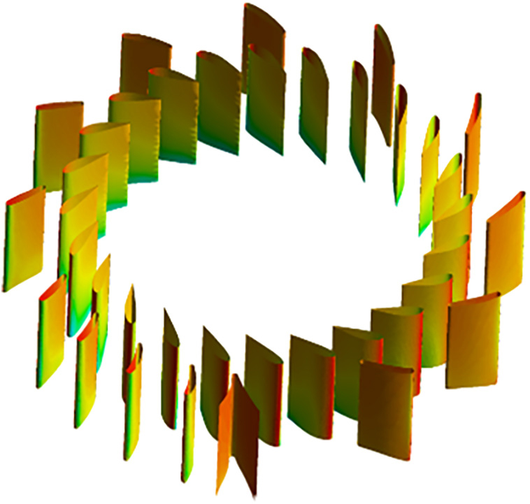
Using CFD techniques to optimize the guide vane geometry is a key strategy for enhancing turbine performance [16]. Based on the functional characteristics of the flow passage and the analyzed CFD results, the proposed modification scheme includes appropriately reducing the guide vane thickness, shortening the trailing portion, and slightly extending the leading edge. It is crucial to note that although the guide vane arrangement maintains geometric symmetry, the modification of the airfoil profile significantly alters the flow velocity triangle. In the original design, the guide vane outflow angle did not match the runner blade inlet angle effectively, leading to a non-zero incidence angle at the runner inlet. In contrast, the modified guide vanes optimize the flow direction (α), ensuring that the fluid enters the runner blades tangentially. This improved flow matching eliminates inlet impact losses and suppresses flow separation within the runner channels. The redesigned adjustable guide vane is shown in Figure 2.

Compared with the current prototype guide vane-characterized by a relatively rounded leading edge and a thick airfoil-the modified geometry features a sharper and slimmer profile. This refinement aims to enhance hydrodynamic performance, reduce hydraulic losses, and increase turbine efficiency [17]. The thinner and sharper leading-edge configuration facilitates smoother flow passage and reduces the likelihood of inlet flow impact, thereby improving operational stability [18]. Moreover, the improved leading-edge shape enables better flow guidance and more uniform flow distribution toward the runner, contributing to enhanced overall turbine performance.
4. RESULTS AND DISCUSSION
4.1. Numerical results and analysis of the original unit
4.1.1. Performance parameters of the original unit
A three-dimensional steady-state numerical simulation of the internal flow field of the original hydraulic turbine at Huilong Hydropower Station is carried out under the condition that the rated head remains unchanged. The key performance parameters obtained from the CFD calculation serve as the baseline for evaluating the effects of the guide vane modification. Under rated conditions, the simulated output is 38,660 kW with a hydraulic efficiency of 92.2%.
4.1.2. Numerical model validation
Due to the long operation history of the Huilong Hydropower Station and commercial restrictions, the complete experimental Hill chart of the original runner is not available for comparison. However, to validate the numerical accuracy, the CFD calculated output under rated conditions was compared with the actual design data of the power station. The simulation predicts a turbine output of 38.66 MW at the rated head of 28 m, which shows a high degree of consistency with the unit’s nominal rated capacity (approx. 37.5 MW generator output plus mechanical and electrical losses). The relative deviation is within 3%, which is acceptable for engineering applications. Furthermore, since this study focuses on the relative performance improvement between the original and modified guide vanes using the identical runner model, the comparative results are considered reliable for guiding the retrofit scheme.
4.1.3. Internal flow field analysis of the original unit
-
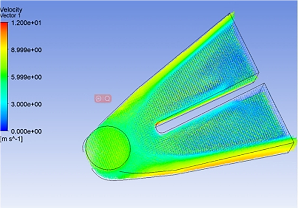
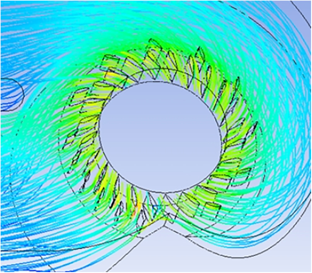
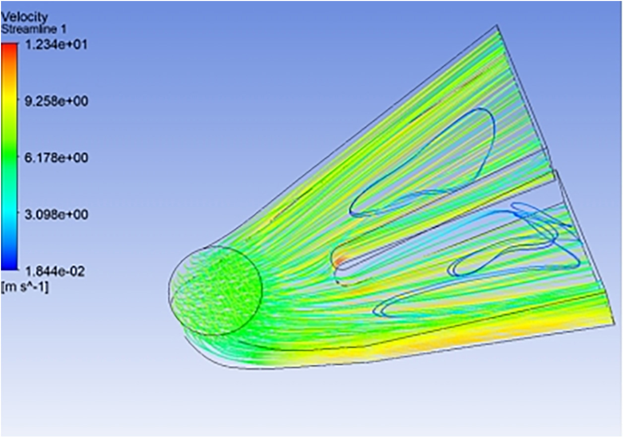
Flow field analysis of the original volute region (Figures 3 and 4).
The results indicate that significant velocity variations and vortex structures appear in the inlet region. The flow trace shows that, after the fluid enters the bend, the flow path is deflected, and flow separation occurs around the circular structure, thus causing potential energy loss. The velocity vector distribution further confirms this phenomenon, although the inlet flow is relatively uniform, the velocity gradient increases notably in the curved and circular zones, where alternating high-speed and low-speed recirculating vortices occur.
-
Flow field analysis of the original guide vane region (Figures 5 to 8).
The results show that the fluid pressure is highest near the inlet and outlet, while the internal region exhibits relatively low pressure. That is, the fluid flows smoothly in this region with small resistance. At the inlet, the flow velocity is high and the streamline distribution is uniform, indicating good flow behavior. However, the pressure distribution on the guide vane surfaces is non-uniform, which requires further optimization to reduce its adverse influence on the flow field.
-
Flow field analysis of the original runner region (Figure 9).
The results indicate that the relative velocity on the suction side of the blade is generally uniform, however, velocity variations occur in the bending region due to flow attachment or separation, which thus affects flow stability. The velocity vectors show that the inlet velocity is relatively high and then gradually decreases along the blade surface. Local low-velocity zones or vortices may occur, which would deteriorate the hydraulic performance [19]. In severe cases, such low-velocity or recirculation regions will lead to energy loss and reduce the overall efficiency.
-
Flow field analysis of the original draft tube region (Figures 10 to 12).
The results demonstrate that the flow condition in the draft tube is favorable. The pressure decreases smoothly from the inlet to the outlet, with no abrupt changes or blockage. The flow path is continuous, without large vortices or separation, and the flow field remains stable, which helps reduce energy loss. The fluid velocity distribution is uniform, and the velocity gradually increases along the draft tube.




4.2. Numerical results and analysis of the upgraded unit
A three-dimensional steady-state CFD turbulence simulation was conducted for the entire flow passage of the turbine after the guide vane modification. The objective is to predict the hydraulic performance of the upgraded unit and provide a basis for determining the final modification scheme [20].
4.2.1. Performance parameters of the upgraded unit
Under the condition that the rated head and flow rate remain unchanged, a 3D steady-state simulation of the internal flow field was performed. The calculation results indicate that the turbine output has increased to 38,866 kW, and the hydraulic efficiency has improved to 92.5%.
4.2.2. Internal flow field analysis of the upgraded unit
-
Flow field analysis of the oupgrade volute region (Figures 13 and 14).
The pressure distribution inside the volute exhibits good circumferential symmetry and decreases smoothly from the inlet toward the outlet along the radial direction. The pressure contours are continuous without abrupt fluctuations. Correspondingly, the velocity magnitude increases uniformly with decreasing pressure, and the circumferential distribution remains symmetric, indicating a uniform inflow into both the volute and the guide vane mechanism. The internal flow is smooth, with no obvious vortex structures, resulting in low hydraulic loss.
-
Flow field analysis of the oupgrade guide vane region (Figures 15 and 16).
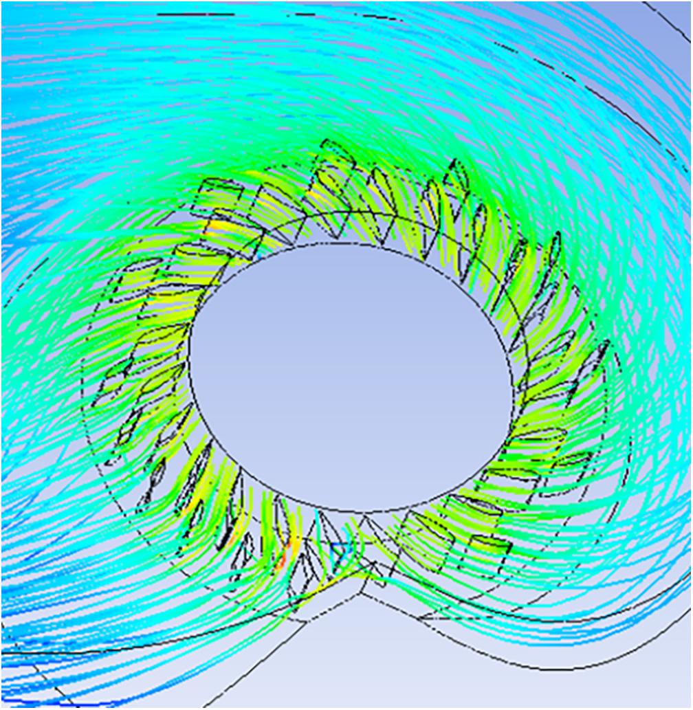
The pressure in the guide vane channels decreases uniformly from the fixed guide vane inlet to the movable guide vane outlet at the rated condition. The comparison results demonstrate that the modified design effectively eliminates the flow separation and disordered streamlines on the suction side of the fixed guide vanes. The streamlines attached to the blade surfaces are smooth and continuous. Furthermore, the impact-induced separation at the inlet of the adjustable guide vanes, which was present in the original unit, is no longer evident. This indicates that the optimized thinner airfoil profile significantly reduces hydraulic losses caused by local vortex structures.
-
Flow field analysis of the oupgrade runner region (Figures 17 and 18).
The static pressure on the working surface of the runner blades is consistently higher than that on the suction side, with no closed pressure contours, indicating normal pressure gradients. The pressure distribution is smooth across the entire blade surface.The streamline patterns show uniform and stable flow acceleration through the runner, meeting the requirements for efficient energy conversion and confirming the improved flow conditions resulting from the guide vane modification.
-
Flow field analysis of the oupgrade draft tube region (Figures 19 and 20).
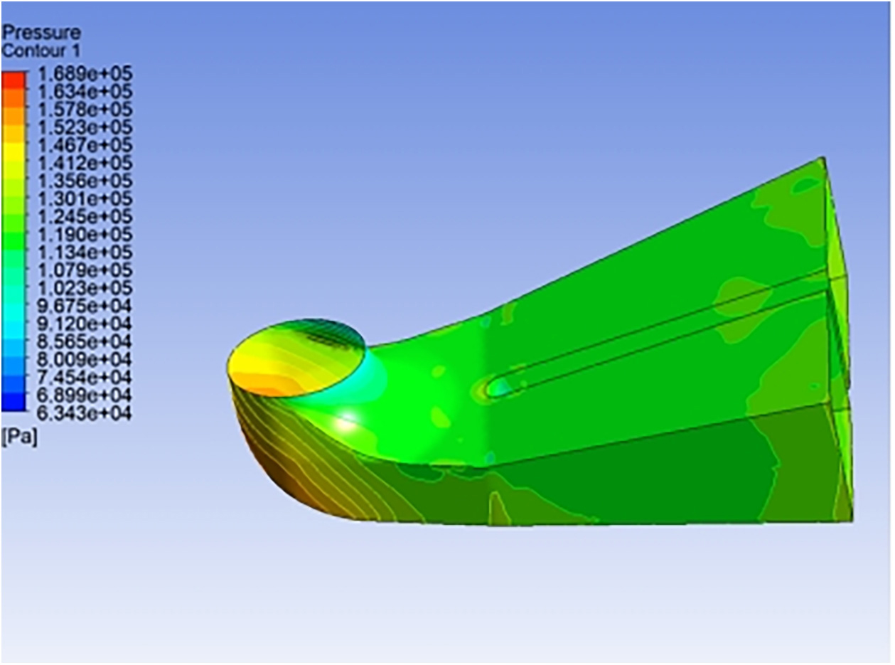
The pressure distribution in both radial and circumferential directions is uniform, with no pronounced high- or low-pressure zones, ensuring stable flow behavior. The velocity is relatively high at the draft tube inlet and gradually decreases along the main flow direction, while the overall streamline pattern remains smooth and stable. This indicates effective energy recovery and favorable hydraulic performance in the draft tube of the upgraded unit.
-
Comprehensive planar flow field analysis of the upgraded unit (Figures 21 to 24).
To provide a more comprehensive discussion of the results as required for in-depth evaluation, the pressure contours and velocity vectors on two critical selected planes of the upgraded model were further analyzed. On the horizontal central plane, the pressure distribution in the spiral casing remains highly symmetric and decreases smoothly towards the runner. The velocity vectors demonstrate that the fluid passes through the modified thinner guide vanes smoothly, without obvious impact, flow separation, or wake blockage at the runner inlet. This planar view confirms that the newly designed airfoil effectively rectifies the flow angle.
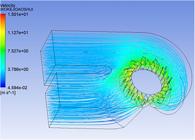
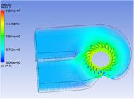


On the vertical central plane, the overall downward flow behavior is illustrated. The pressure transitions smoothly from the runner cone down into the draft tube. Most notably, the velocity vectors in the draft tube elbow region reveal a well-guided flow path. Severe large-scale vortices or severe recirculation zones, which typically cause hydraulic instability, are absent in this plane. This comprehensive planar evidence proves that the upgraded turbine achieves highly favorable internal flow conditions.
4.3. Comprehensive performance comparison and discussion
4.3.1. Comparison of hydraulic performance
To quantitatively evaluate the effectiveness of the retrofit scheme, the key performance indicators of the upgraded unit were compared with those of the original unit under the same rated operating conditions. The results are summarized in Table 2.
4.3.2. Significance of the performance improvement
While this efficiency magnitude might appear to fall within the uncertainty range of standard RANS simulations, the relative improvement is considered reliable and theoretically significant for the following reasons:
-
(1)
Robust Comparative Methodology: This study employs a strictly comparative methodology. Both the original and modified cases utilize identical mesh topologies and numerical schemes. Consequently, systematic errors inherent in the CFD model tend to cancel out, making the predicted trend and performance delta robust.
-
(2)
Validation of Design Principle: While the numerical gain (0.3%) is marginal, it serves as a critical validation of the proposed Inverse Design Strategy. The positive result confirms that correcting the guide vane outflow angle to match the runner inlet is physically correct. It demonstrates that the hydraulic losses have been successfully reduced, validating the scientific feasibility of the profile modification.
-
(3)
Flow Stability Verification: The validation of the new design is not solely based on efficiency numbers but also on the qualitative improvement of the flow field. The elimination of flow separation in the guide vanes and the removal of impact at the runner inlet confirm that the hydraulic instability has been significantly suppressed. This reduction in unstable flow structures is critical for minimizing vibration and extending the fatigue life of the runner, which is a key technical indicator in retrofit evaluations.
5. CONCLUSIONS
Based on the practical requirements of the Huilong Hydropower Station renovation project, this study conducted a comprehensive feasibility analysis of a guide vane modification scheme. Using a combined SOLIDWORKS modeling and ANSYS-CFD simulation approach, the potential gains and engineering implications were rigorously evaluated. The following conclusions are drawn:
-
(1)
A split-assembly parametric modeling strategy was established using SOLIDWORKS. This method proved to be efficient and flexible, overcoming the limitations of conventional modeling by ensuring high geometric fidelity and smooth flow passage surfaces for the complex turbine assembly.
-
(2)
The CFD results verified the hydraulic validity of the proposed modification. By thinning the airfoil and sharpening the trailing edge, the modified design effectively optimized the velocity triangle matching and suppressed flow separation at the runner inlet. However, the quantitative analysis indicated that under the constraint of a fixed runner, the resulting efficiency gain was approximately 0.3%. This suggests that the turbine’s overall performance is relatively insensitive to minor changes in guide vane profile when the runner geometry remains unchanged.
-
(3)
Although the modification demonstrated hydraulic improvements, the cost-benefit analysis leads to a prudent engineering decision. Considering that the modification would require significant adjustments to the mechanical linkage, the marginal efficiency gain (0.3%) does not justify the associated engineering costs and risks. Therefore, for this specific retrofit project, it is recommended to retain the original guide vane dimensions.
-
(4)
Regarding the design methodology, the inverse design approach adopted in this study proved to be a highly effective decision-support tool. It successfully identified the performance limits and prevented uneconomical modifications. Future work could improve this procedure by integrating automated multi-objective optimization algorithms to simultaneously redesign the guide vanes and the runner, potentially unlocking larger efficiency gains that justify implementation.
6. ACKNOWLEDGMENTS
The authors appreciate the support from Tianjin Sino-German University of Applied Sciences and the Tianjin Science and Technology Program (Nos. 25YFYFFG00340 and 25YFYFFG01640).
We sincerely thank the anonymous referees for their insightful feedback that helped refine and enhance the present manuscript.
7. BIBLIOGRAPHY
-
[1] NIKOLIĆ, M.V., KARAMARKOVIĆ, R.M., KARAMARKOVIĆ, M.V., et al, “Retrofit of a settling basin of a small hydropower plant”, Engineering Structures, v. 236, pp. 112118, 2021. doi: https://doi.org/10.1016/j.engstruct.2021.112118.
» https://doi.org/10.1016/j.engstruct.2021.112118 - [2] MICHEL, B., COUSTON, M, SABOURIN, M., Hydro turbines rehabilitation, Grenoble, École Nationale Supérieure de l’Énergie, pp. 3–12, 2004.
-
[3] KUMARI, R., PRABHAKARAN, K.K., DESINGU, K., et al, “Improved hydroturbine control and future prospects of variable speed hydropower plant”, IEEE Transactions on Industry Applications, v. 57, n. 1, pp. 941–952, 2021. doi: https://doi.org/10.1109/TIA.2020.3028798.
» https://doi.org/10.1109/TIA.2020.3028798 -
[4] WU, J., SHIMMEI, K., TANI, K., et al, “CFD-based design optimization for hydro turbines”, Journal of Fluids Engineering, v. 129, n. 2, pp. 159–168, 2007. doi: https://doi.org/10.1115/1.2409363.
» https://doi.org/10.1115/1.2409363 -
[5] SEMENOVA, A., CHIRKOV, D., LYUTOV, A., et al, “Multi-objective shape optimization of runner blade for kaplan turbine”, IOP Conference Series. Earth and Environmental Science, v. 22, n. 1, pp. 012025, 2014. doi: https://doi.org/10.1088/1755-1315/22/1/012025.
» https://doi.org/10.1088/1755-1315/22/1/012025 -
[6] MÜLLER, J.S., LÜCKOFF, F., KAISER, T.L., et al, “On the relevance of the runner crown for flow instabilities in a Francis turbine”, IOP Conference Series. Earth and Environmental Science, v. 1079, n. 1, pp. 012053, 2022. doi: https://doi.org/10.1088/1755-1315/1079/1/012053.
» https://doi.org/10.1088/1755-1315/1079/1/012053 -
[7] OHIEMI, I.E., MCNABOLA, A., “Design optimisation of legacy francis turbine using inverse design and CFD: a case study of bérchules hydropower plant”, Energies, v. 18, n. 21, pp. 5602, 2025. doi: https://doi.org/10.3390/en18215602.
» https://doi.org/10.3390/en18215602 -
[8] SHRESTHA, R., SHRESTHA, K., CHITRAKAR, S., et al, “Evaluation of different erosion models for predicting guide vane wear in Francis turbine”, Frontiers of Mechanical Engineering, v. 11, pp. 1542074, 2025. doi: https://doi.org/10.3389/fmech.2025.1542074.
» https://doi.org/10.3389/fmech.2025.1542074 - [9] LAI, X.D., JI, L., LI, Q.G., et al, “A new approach for retrofit of hydraulic turbines with numerical simulation”, Water Resources and Hydropower Engineering, v. 36, n. 6, pp. 81–84, 2005.
-
[10] GAO, J., DAI, L., LIU, X., et al, “Variable-speed hydropower generation: System modeling, optimal control, and experimental validation”, IEEE Transactions on Industrial Electronics, v. 68, n. 11, pp. 10902–10912, 2021. doi: https://doi.org/10.1109/TIE.2020.3031528.
» https://doi.org/10.1109/TIE.2020.3031528 - [11] HU, X.C., ZHANG, S.Q., HE, S.H., “Three-dimensional numerical simulation for runners with long and short blades of turbine”, Hydroelectric Power, n. 6, pp. 47–49, 2009.
- [12] LI, S.X., CHANG, J.Q., “Computer fluid simulation calculation before turbine transformation in hua’an hydropower plant”, Mechanical & Electrical Technique of Hydropower Station, v. 36, n. 4, pp. 4–8, 2013.
-
[13] HUANG, J., ZHU, M., DUAN, J., et al, “Study on the modal characteristics of runner with cracked blade for Francis turbine under the effect of fluid”, Measurement Science & Technology, v. 36, n. 5, pp. 056117, 2025. doi: https://doi.org/10.1088/1361-6501/adc1ed.
» https://doi.org/10.1088/1361-6501/adc1ed -
[14] LU, J., TAO, R., XIAO, W., et al, “Analysis of flow and energy dissipation in pump turbine with small guide vane opening”, Engineering Applications of Computational Fluid Mechanics, v. 18, n. 1, pp. 2421481, 2024. doi: https://doi.org/10.1080/19942060.2024.2421481.
» https://doi.org/10.1080/19942060.2024.2421481 - [15] GAO, Y., “Optimization of installation process of turbine runner”, Modern Manufacturing Technology and Equipment, v. 60, n. 10, pp. 119–122, 2024.
- [16] PATEL, V. A., JAIN, S. V., MOTWANI, K. H., et al, “Numerical optimization of guide vanes and reducer in pump running in turbine mode”, Procedia Engineering, v. 51, pp. 797–802, 2013.
- [17] HE, X.M., TAN, S.H., “Analysis and treatment of abnormal sound at draft tube manhole door of francis units”, Mechanical & Electrical Technique of Hydropower Station, v. 47, n. 11, pp. 96–99, 2024.
-
[18] POKHAREL, N., THAPA, B.S., SOLEMSLIE, B.W., et al, “Design and numerical study of a pump-turbine for retrofitting of an existing francis turbine”, Journal of Physics: Conference Series, v. 2629, n. 1, pp. 012011, 2023. doi: https://doi.org/10.1088/1742-6596/2629/1/012011.
» https://doi.org/10.1088/1742-6596/2629/1/012011 - [19] SUN, J., ZHOU, X.J., MA, E.J., “CFD hydraulic analysis of shimen power plant renovation runner”, In: Proceedings of the 2015 Industrial Design and Collaborative Innovation Conference, pp. 156–163, 2015.
-
[20] LI, Q., XIN, L., XIE, G., et al, “Influence of guide vane profile change on draft tube flow characteristics of water pump turbine”, Processes, v. 10, n. 8, pp. 1494, 2022. doi: https://doi.org/10.3390/pr10081494.
» https://doi.org/10.3390/pr10081494