 Numerical analysis of the performance of beam-column connection using hidden steel corbel in precast concrete structures
Abstract
Abstract Precast concrete construction has advantages over conventional in situ methods, including short construction time and improved quality control. The performance of precast construction heavily relies on its connections, whose lack of knowledge can lead to oversimplified and conservative designs. This study uses a FEM-based numerical model to evaluate the performance of a beam-to-column connection with a double-sided steel hidden connector and top continuous bars. Experimental and analytical studies validated this model, considering moment-rotation diagrams. The connection was classified as a medium-strength semi-rigid connection, similar to the reference study. The moment-rotation diagram closely aligned with experimental results, with errors ranging from 5% to 13% at the yield of the top bars. The discrepancies between the results may stem from simplifications in the simulation, e.g., symmetry assumptions, constitutive models, and interactions. A parametric analysis was conducted considering (i) the yield stress of the connector, (ii) the steel reinforcement ratio of the top bars, (iii) the presence of stirrups over the connector, and (iv) the addition of welded bars to the hidden corbel. Increasing the yield stress of the connector and the reinforcement ratio of the top bars, as well as adding stirrups over the connector, enhanced the connection properties. The use of welded bars to the corbel did not affect the results. The reinforcement ratio had the most significant impact. In conclusion, the proposed numerical model provided an efficient analysis of the beam-to-column connection and could contribute to refine the current designs.
Keywords:
beam-to-column connection; billet; numerical model; hidden steel corbel; precast concrete structure
Resumo
Resumo A construção em concreto pré-moldado traz vantagens sobre os métodos in loco convencionais, como menor tempo de construção e melhor controle de qualidade. O desempenho das estruturas pré-moldadas depende fortemente de suas ligações, cujo lacuna de conhecimento pode levar a projetos simplificados e conservadores. Este estudo avalia o desempenho de uma ligação viga-pilar com um conector metálico embutido de dupla face e armaduras de continuidade superiores, por meio de um modelo numérico baseado em MEF. Estudos experimentais e analíticos validaram esse modelo, utilizando diagramas momento-rotação. A ligação foi classificada como semirrígida de resistência média, análogo ao estudo de referência. O diagrama momento-rotação apresentou boa concordância com os resultados experimentais, com erros de 5% a 13% no momento do escoamento das armaduras de continuidade. As discrepâncias podem advir de simplificações da simulação, como adoções de simetria, modelos constitutivos e interações. Foi realizada uma análise paramétrica considerando (i) a tensão de escoamento do conector, (ii) a taxa de aço das armaduras de continuidade, (iii) a presença de estribos sobre o conector e (iv) a adição de barras soldadas ao consolo embutido. O aumento de todos os parâmetros melhorou as propriedades da ligação, exceto as barras soldadas, que não modificaram os resultados. A taxa de aço teve o impacto mais significativo. Em conclusão, o modelo numérico proposto proporcionou uma análise eficiente da ligação viga-pilar e pode contribuir para aprimorar os projetos atuais.
Palavras-chave:
ligação viga-pilar; tarugo; modelo numérico; consolo metálico embutido; estrutura de concreto pré-moldado
1 INTRODUCTION
Precast concrete elements primarily rationalize the erection of structures, as their production occurs in a different position from their final use [1]. Precast concrete is associated with the country’s developmental stage, as well as the quality and sustainability requirements of its population. Consequently, its use is increasing in emerging countries like Brazil [2].
The structural performance of precast concrete elements relies on their connections, which dictate design and erection constraints [3]. These connections transfer loads between elements, restrain frame movement, and contribute to structural stability [4]. Therefore, they must exhibit adequate strength, ductility, and stiffness [5]. The presence of top continuous bars in connections impacts strength and ductility, for example, while the transfer level of forces and moments affects the connection stiffness [6].
Beam-to-column connections exhibit the most complex designs and constructions. Their moment transfer (flexural stiffness) classifies them as pinned, semi-rigid, and rigid connections. Pinned connections allow relative rotations between precast concrete elements without moment transfer, resulting in simpler designs. In contrast, rigid connections have more complex designs as they promote moment transfer and restrict rotations. However, most connections are semi-rigid, exhibiting intermediate performance between rigid and pinned connections, with partial moment and rotation transfer [3].
To classify beam-to-column connections, ABNT NBR 9062 [7] standard defines the rotation restraint factor using Equation 1. The rotation centers of the beams determine their effective span , while their secant stiffness considers a simplified physical nonlinearity. The secant flexural stiffness of the connection is calculated using the moment-rotation ratio corresponding to the yield point of the continuous bars. Semi-rigid connections have values ranging from 0.15 to 0.85. Connections with above 0.85 are rigid, while those below 0.15 are articulated.
For specific connection types, ABNT NBR 9062 [7] determines for negative bending using Equation 2. The standard provides adjustment coefficients and effective lengths of deformation due to elongation of the top continuous bars for some connection types. Equation 2 also considers the area , modulus of elasticity , and effective height of these bars.
One connection type addressed in ABNT NBR 9062 [7] considers a billet-type connector. These hidden connections offer aesthetic benefits, facilitate adding more beams to columns, prevent conflicts with other projects, and protect steel parts. In general, their structural mechanism involves shear strength at the discontinuity plane with the beams, transferring shear forces to the columns, where there are compression forces [3].
Variations in connector sections affect connection performance only when associated with changes in the positions and strengths of other resistance mechanisms, such as welds and bolts, because they modify lever arms [8], [9]. However, the billet’s arrangement has a more significant impact on connection strength. In an external column setup (single-sided connection), bar anchorage is less effective, reducing strength compared to an internal column setup (double-sided two-way connection) [9].
Welding vertical bars to the embedded steel corbel, particularly in an external column setup, can also enhance the strength and stiffness of billet-type connections [8]. Analytical models consider this addition to connection strength but overlook the influence of top continuous bars and slabs, despite their impact on connection properties [3]–[5]. Moreover, these models neglect other resistance mechanisms, as welds and bolts, leading to conservative predictions [10]. FIB [11] incorporates top continuous bars and filling material (grout) to determine the negative moment resistance of billet-type connections using Equation 3, that includes the billet width , yield stress , and the characteristic compressive strength of the grout .
While analytical models are known for conservative predictions, extensive experimental tests are burdensome. As an alternative, numerical models have gained prominence with advancements in computational capabilities, using differential equations to address the characteristics of physical problems. Hence, it is essential to carefully balance model simplifications to ensure representativeness.
Bahrami et al. [12] developed a numerical model as a preliminary study of a connection with a hidden steel corbel, optimizing the subsequent experimental analysis. Additionally, Hashim and Agarwal [13] compared the performance of some connections using simulations. Numerical models also allowed the validation and expansion of test results through parametric analysis, although the lack of data on interactions remains a critical point [14], [15]. These studies indicate that numerical results often predict slightly higher connection stiffness than experimental data, but the differences are within acceptable ranges, demonstrating their accuracy in representing hidden steel corbel connections.
This paper assesses the structural performance of a billet-type connection in an internal column setup using numerical models based on the finite element method (FEM), with Abaqus 2021 software. First, the validation references experimental [16] and analytical [11] studies. Finally, the parametric analysis extrapolates the results to analyze the impact of four factors in connection behavior: (i) the yield stress of the connector, (ii) the steel reinforcement ratio of the top bars, (iii) the presence of stirrups over the connector, and (iv) the addition of welded bars to the hidden steel corbel.
2 METHODOLOGY
The methodology includes simplifications and assumptions in the numerical model of a billet-type connection, aiming to balance accuracy and computational cost. The following aspects define the connection’s geometry, constitutive models, interactions, finite element meshes, and boundary conditions.
2.1 Geometry
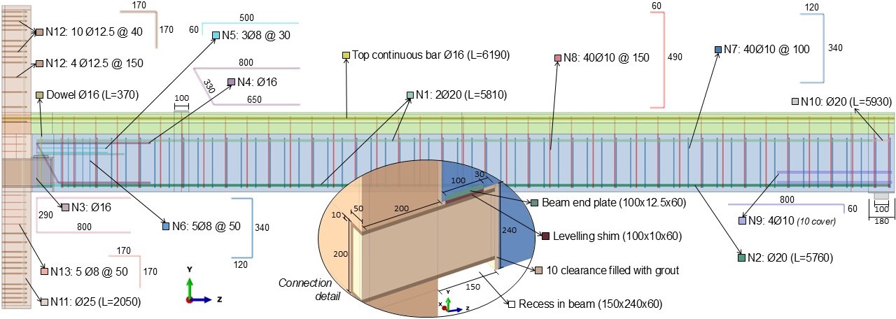
Figure 1 provides a schematic representation of the connection tested by Bachega [16]. The precast column had a 400 mm square cross-section and was 2100 mm long. The billet connector, filled with grout, measured 200 mm x 100 mm x 10 mm and was 700 mm long. The precast beams were 5980 mm long with a cross-section of 300 mm X 400 mm, leaving a 10 mm clearance between them and the column. Cast-in-place concrete above the beams was 150 mm high. More details are available in Bachega [16].
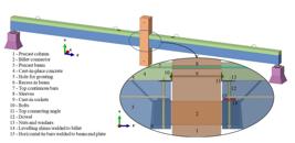
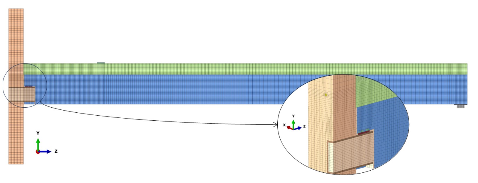
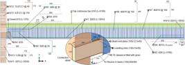
The three-dimensional numerical model employed symmetries in the XY and YZ planes to reduce processing time [12]–[15]. Additional simplifications were: (i) disregarding lifting details, as they had a negligible impact on structural behavior, (ii) representing the beam’s support with an elastomer component (180 mm x 180 mm x 10 mm), a steel plate (100 mm x 100 mm x 41 mm), and boundary conditions, (iii) modeling the dowel attachment through interactions, as this joint only aimed for temporary stability, and (iv) shaping a quadrangular prismatic recess in the beam without the grouting hole to avoid convergence problems. Figure 2 details the numerical model.
2.2 Constitutive models
The simulation used the isotropic elastoplasticity model with Von Mises yield criteria for the steel parts. Table 1 lists their input properties from the literature, including yield strength , Young’s modulus , and Poisson’s ratio , as Bachega [16] did not test the steel. However, the author tested concrete properties, shown in Table 1, including the mean compressive strength at 28 days , , and . Concrete Damage Plasticity (CDP) modeled these parts, accounting for failure through compressive crushing and tensile cracking, based on stress-strain diagrams from FIB [17]. Previous studies on similar connections demonstrated the accuracy and robustness of CDP in representing concrete [12], [14].
The CDP parameters included an eccentricity of 0.1, a ratio of 2/3, a viscosity parameter of 0.001, and a ratio of initial biaxial compressive stress to initial uniaxial compressive stress of 1.16. These values are commonly used for concrete in the literature [24] and were considered appropriate for this model. The dilation angle was set to 36°, within its typical range of 36° to 40° [25], and the model exhibited low sensitivity to variations within this interval.
The analysis included a hyperelastic model for the elastomer component, as nearly incompressible materials ( ≈ 0.5) could cause numerical sensitivity and convergence issues [24]. Rezende et al. [26] verified the close agreement between experimental tests and Yeoh model results, providing material input parameters ( = 0.605, = 0.0249, = -0.00025) and compressibility values (= 0.0083), which were used in this analysis.
2.3 Interactions
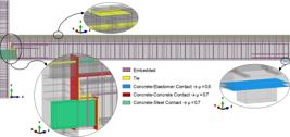
Literature commonly employs embedded constraints for reinforcements, assuming full bonding with concrete [12], [13]. However, full bonding of the top continuous bar increased connection stiffness compared to the test data. Thus, other bars and the beam end plate addressed the embedded constraint, while the top continuous bar incorporated a concrete-steel contact along the billet projection (150 mm), with a tie constraint in its other sections [27]. The analysis also applied interactions for other interfaces, using hard contact for normal behavior and penalty formulation for tangential behavior. Figure 3 shows the interactions and friction coefficients [12], [28].
2.4 Finite element mesh
Since reinforcements primarily work in the axial direction, T3D2 truss elements (2-node linear displacement) effectively predicted their behavior, except for the dowel, N8 stirrups, and top continuous bar. The dowel and N8 stirrups experienced shear forces, so B31 elements (2-node linear beam) modeled them. Due to the simulation’s complexity, the top continuous bar and remaining parts (e.g., concrete units, billet, plates) received C3D8R solid hexahedral elements (8-node linear brick, reduced integration with hourglass control), which reduced processing time and avoided shear locking distortion. The elastomer component employed C3D8RH formulation, as the hybrid approach mitigated the numerical sensibility of nearly incompressible materials.
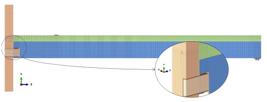
The components (e.g., beam, column) were sectioned to optimize mesh density based on geometry, convergence, and processing time requirements. The mesh assignment ensured a smooth transition between adjacent regions to avoid numerical integration inaccuracies, but contact interactions allowed for varying mesh densities at each interface. Therefore, the connection area had a finer mesh (elements dimensions around 10 mm), while less critical regions used coarser meshes (about 30 mm for the column and 50 mm for the beam). Larger finite elements led to convergence problems due to significant stress and strain increments in constitutive and interaction models, while smaller ones increased processing time. Figure 4 shows the final mesh of the model, with 140,724 finite elements and 169,131 nodes.
2.4 Boundary conditions
Since solid finite elements do not include rotational degrees of freedom, symmetry conditions in the XY and YZ planes restricted displacements in the Z () and X () directions, respectively. For beam finite elements (dowel and N8 stirrups), YZ symmetry restricted rotations around Y () and Z () axes. To replicate test conditions, , , and were constrained at the bottom of the column, allowing at the top. For the beam’s hinged support, only the central line of the steel plate was constrained in , , and , allowing its global . Finally, a 100 mm x 60 mm x 12.5 mm plate distributed the load, with initial, minimum and maximum increments of 10-2, 10-15, and 2∙10-2, respectively.
The general static analysis included geometric non-linearity due to the elastomer component, while the constitutive models accounted for physical non-linearity. Finally, the Newton-Raphson method solved the nonlinear system.
3 RESULTS AND DISCUSSIONS
3.1 Validation
First, the numerical model was validated against the experimental results of Bachega [16], using moment-rotation diagrams. Bachega [16] quantified moments M regarding the column face, according to Equation 4. Load cell measurements and corresponded to the center of the load plate (1045 mm from the column face) and the beam support (5900 mm from the column face), respectively. The moments excluded the dead loads due to the constructive sequence of Bachega’s [16] test.
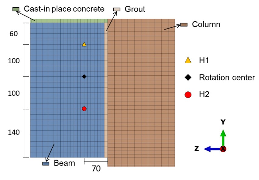
Bachega [16] measured the rotations using a clinometer at the connection’s pivot point. Since the numerical model could not quantify point rotation, it calculated based on horizontal displacements, and , equally spaced from the pivot point, using Equation 5. Figure 5 shows this setup on the beam’s external face, similar to the clinometer locations in the test.
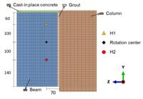
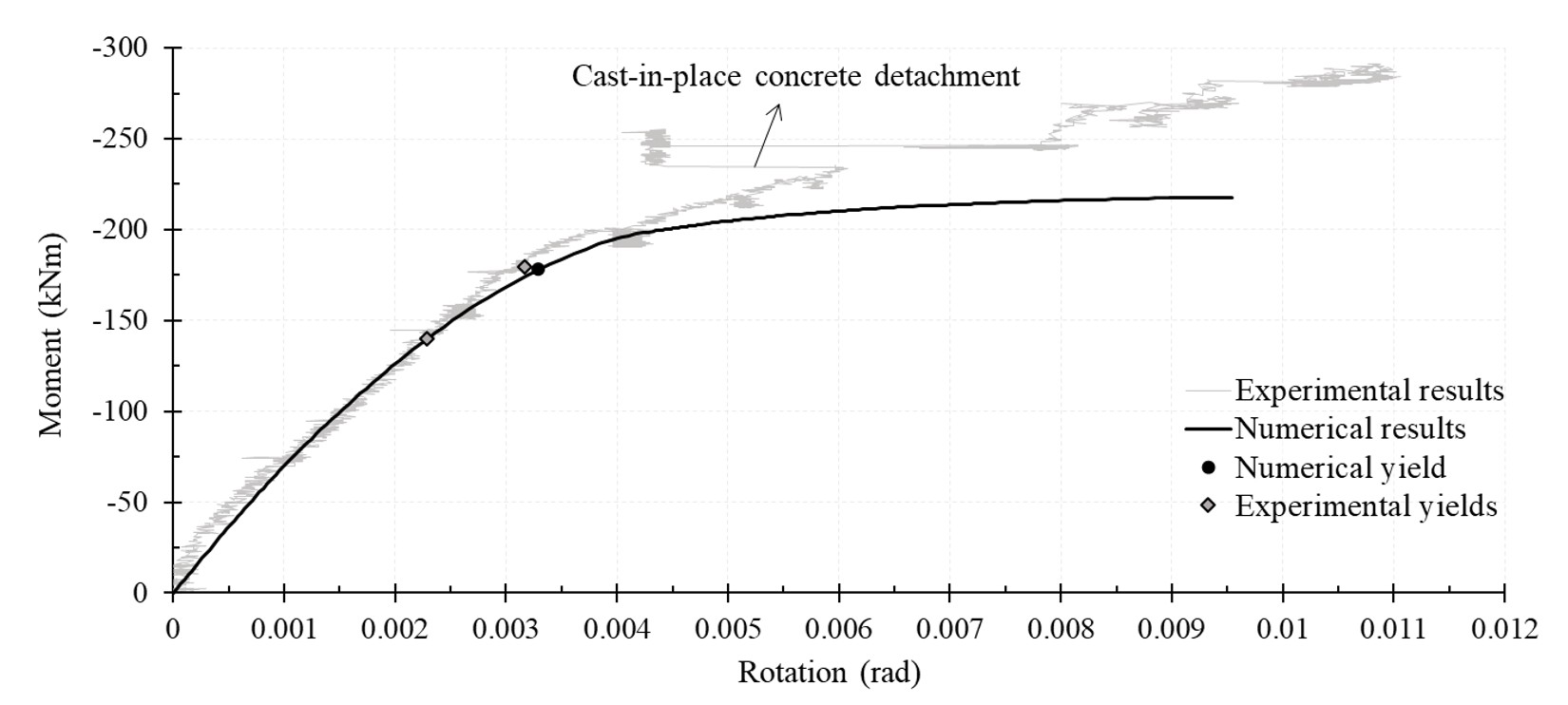
Figure 6 compares the moment-rotation diagrams from experimental and numerical studies. Initially, the numerical model closely matched the test results. However, it diverged in the final phase of the test, which showed excessive cracking and strains, leading to detachment and rupture of the cast-in-place concrete at moments of -234 kNm and -291 kNm, respectively. In contrast, the numerical model’s ultimate moment was -218 kNm, differing from the test results by 7% and 25%. In the test, detachment occurred after a 350 kN load, whereas in the simulation, it was incremental and accelerated after the top continuous bar yielded. Additionally, using literature values for elastomer and steel components, particularly for the top continuous bar and the billet, influenced the results.
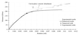
Figure 6 highlights the top continuous bar yielding in experimental and numerical studies. The symmetry assumption led to a single yielding point at -178 kNm, while the test showed two values, -140 kNm and -180 kNm. At this yield point, analytical prediction from FIB [11] estimated a resistant moment of -109 kNm, through Equation 3. Input values were 570 MPa for , 55.1 MPa for , 100 mm for , 507 mm for , and 402.12 mm2 for . Despite omitting safety coefficients, the analytical result was significantly lower than experimental and numerical values. This discrepancy arises because the FIB [11] model considers only two resistance mechanisms (top continuous bar and grout), while other parts, e.g. the billet, had significant influence in numerical and experimental studies.
The moment-rotation ratio at the top continuous bar’s yielding () defines for experimental and numerical results. The ABNT NBR 9062 [7] standard analytically determines using Equation 2, which input values were 0.75 for , 400 mm for , 402.12 mm2 for , 200000 MPa for , and 507 mm for . Table 2 shows the values for each study. The numerical model’s stiffness closely matched the test results, with differences between 5% and 13%. In contrast, the analytical result was again lower than the other values, primarily due to the adjustment coefficient , which promoted design safety through conservatism.
Table 2 also shows the rotation restraint factors calculated using Equation 1. The same values of (5830 mm) and (7.01∙1010 kNmm) were applied to numerical, analytical and experimental studies. Although the lower analytical factor, all approaches were classified as medium-strength semi-rigid connections, consistent with previous research [10], [14], [29].
3.2 Parametric analysis
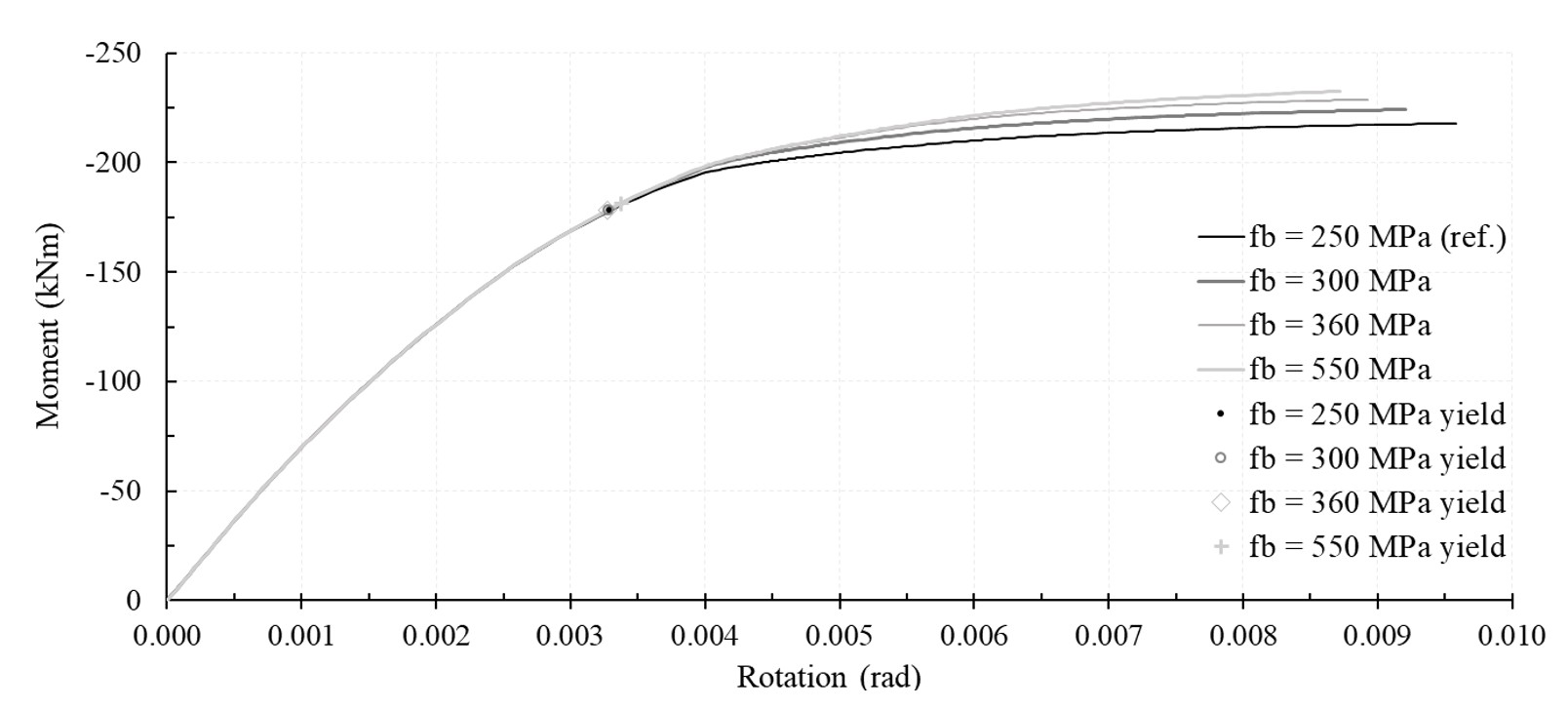
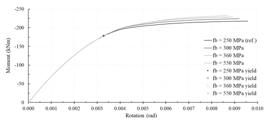
The numerical model validation highlighted the influence of the billet’s yield stress on responses. Due to the lack of experimental data from Bachega [16], a nominal of 250 MPa was assumed [22]. However, similar studies reported values ranging from 260 MPa to 360 MPa [19], [20], [30], [31]. Therefore, Figure 7 shows the moment-rotation diagrams for of 250 MPa, 300 MPa, 360 MPa, and 550 MPa, the last meaning the maximum tensile strength of A36 steel [22]. Increasing only affected the connection behavior after the top continuous bar’s yielding, resulting in the same stiffnesses across models. The initial increment in raised ultimate moment values from -218 kNm to -224 kNm. However, the final larger increment resulted in a smaller increase from -229 kNm to -232 kNm, as the connector did not yield, while the top continuous bar limited the ultimate moment.
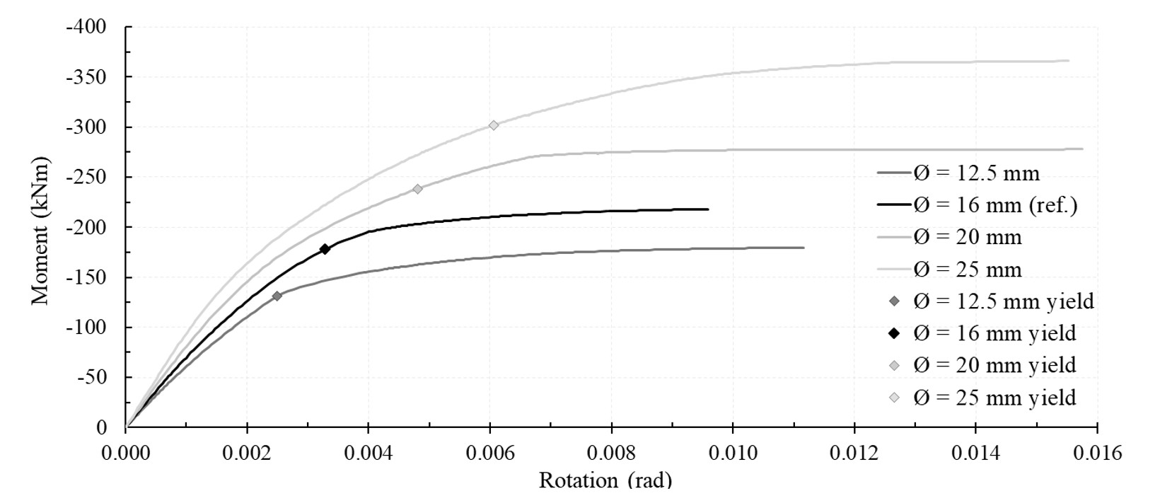
In addition, the top continuous bar analysis focused solely on reinforcement ratio, as its yield stress did not significantly vary in the literature. To optimize processing time and mesh discretization, this study examined changes in diameters , with adjustments in N8 stirrup positions. Figure 8 presents the moment-rotation curves for diameters of 12.5 mm, 16 mm, 20 mm, and 25 mm, adhering to ABNT NBR 6118 [32] design limits.
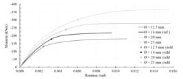
Increasing the reinforcement ratio significantly enhanced the connection behavior in terms of ultimate and yield moments. Table 3 shows an upward trend in connection stiffness and rotation at the top continuous bar yielding. However, stiffness decreased between diameters of 16 mm and 20 mm because, up to 16 mm, the top continuous bar yielded before the billet, whereas after 20 mm, the billet yielded first, altering the connection performance. Therefore, while the reinforcement ratio had a substantial impact on responses, its interaction with the billet yield was also significant.
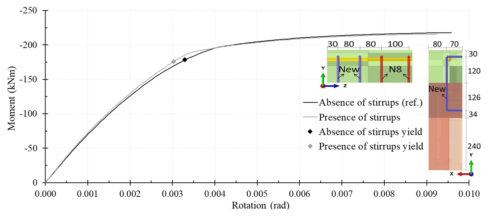
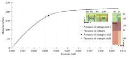
In the experimental test of Bachega [16], failure was primarily due to the detachment of cast-in-place concrete. To mitigate this, the author recommended increasing the top continuous bar ratio, previously analyzed in Figure 8 and Table 3, and adding stirrups over the connector. Based on Bahrami et al. [12] and Hashim and Agarwal [13], the analysis added two 10 mm stirrups over the connector as beam elements, preserving the same material, interface, and boundary conditions of the N8 stirrups. Figure 9 presents the new arrangement and the resulting moment-rotation curve. Therefore, this modification reduced connection rotation by constraining slippage between the cast-in-place concrete and the beam, thereby increasing connection stiffness by approximately 8%.
Finally, since vertical bars welded to the hidden connector enhanced connection performance in the tests conducted by Marcakis and Mitchell [8] and Bahrami et al. [12], this parameter was also analyzed in the present study. To accommodate the cover, the welded bars were spaced 300 mm apart in a symmetrical setup, using bars with a diameter of 20 mm. The basic anchorage length was calculated using Equation 6 from Eurocode 2 [18] to ensure proper anchorage. Given their compression and vertical arrangement, the welded bars showed good anchorage conditions. In Equation 6, a design yield strength of 434.78 MPa for the additional bars and a design tensile strength of 3.99 MPa for the column concrete were used, resulting in a of 242.34 mm.
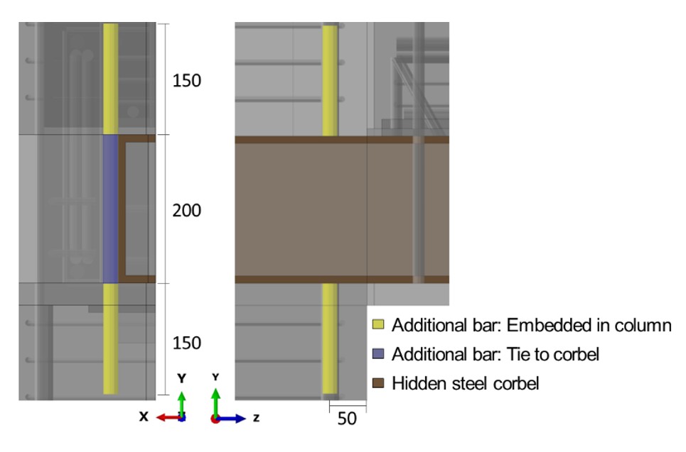
According to Elliott [3], at least half of must overlap the hidden steel corbel at both the top and bottom. Therefore, a length of 150 mm was used, as shown in Figure 10. Again, the numerical model applied only one additional bar due to symmetry assumptions. Figure 10 also indicates the interactions attributed to the additional bar, representing the weld to the hidden corbel with a tie constraint, while other sections were embedded in the column.
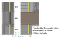
The moment-rotation curve resulting from this new arrangement matched the reference case, indicating that the additional bar did not affect the connection performance. Furthermore, the Von Mises stress on this bar was lower than 42 MPa, reflecting its low solicitation. At first glance, this result appears to contradict the findings of Marcakis and Mitchell [8] and Bahrami et al. [12]. However, Marcakis and Mitchell [8] analyzed an external column setup, while this study focused on an internal setup. Additionally, although Bahrami et al. [12] considered an internal column setup, they applied a horizontal load to the top of the column, causing lateral sliding of the hidden corbel, which required the additional bar. In contrast, for the setup with vertical loads applied to the beams, the concrete column alone resisted the loads.
4 CONCLUSIONS
This paper investigated the performance of a billet-type connection with top continuous bars. The numerical moment-rotation curve showed good initial agreement with experimental results, accurately capturing the yielding behavior and connection stiffness, with differences below 13%. However, analytical predictions and the lack of material data highlighted the complexity of predicting connection performance, resulting in conservative final trends. Overall, the connection was classified as medium-strength semi-rigid, consistent with previous research findings.
The top continuous bar ratio significantly influenced the moments, rotations, and stiffness responses, but its interaction with the yield stress of the hidden connector was also relevant. Current analytical models tend to overlook the connector's contribution, leading to overly conservative designs that undermine the benefits of billet-type connections. While the addition of stirrups over the billet had a smaller impact compared to the top continuous bar ratio, this simplest action increased the connection stiffness by 8% due to additional restraint against slippage between the cast-in-place concrete and the precast beam. Finally, the inclusion of bars welded to the hidden steel corbel did not influence connection performance, mainly due to the internal column setup and the vertical load application.
ACKNOWLEDGEMENTS
The authors gratefully acknowledge the financial support from the Coordenação de Aperfeiçoamento de Pessoal de Nível Superior (CAPES) and grant 2023/15725-2, São Paulo Research Foundation (FAPESP).
-
Financial support:
This study was financed by the Coordenação de Aperfeiçoamento de Pessoal de Nível Superior (CAPES) and grant 2023/15725-2, São Paulo Research Foundation (FAPESP).
-
Data Availability:
The data that support the findings of this study are openly available in SET repository at https://producaocientifica.eesc.usp.br/set/1308?search=th%C3%A1ssia.
-
How to cite:
T. D. Z. Rufato and M. N. Kataoka, “Numerical analysis of the performance of beam-column connection using hidden steel corbel in precast concrete structures,” Rev. IBRACON Estrut. Mater., vol. 18, no. 3, e18304, 2025, https://doi.org/10.1590/S1983-41952025000300004.
REFERENCES
- 1 International Federation for Structural Concrete, FIB Model Code for Concrete Structures, 2023.
- 2 M. K. El Debs, Concreto Pré-Moldado: Fundamentos e Aplicações, 2ª ed. São Paulo: Oficina de Textos, 2017.
- 3 K. S. Elliott, Precast Concrete Structures, 2nd ed. Boca Raton: CRC Press, 2017.
- 4 Precast/Prestressed Concrete Institute, PCI Design Handbook: Precast and Prestressed Concrete. Chicago: PCI, 2010.
- 5 H. Görgün, "An experimental study of the behaviour of double sided bolted billet connections in precast concrete frames," Steel Compos. Struct., vol. 29, no. 5, pp. 603–622, Dec. 2018, http://dx.doi.org/10.12989/scs.2018.29.5.603.
-
6 M. A. Ferreira, “Deformabilidade de ligações viga-pilar de concreto pré-moldado,” Ph.D. dissertation, SET, EESC-USP, São Carlos, SP, 1999. [Online]. Available: https://doi.org/10.11606/T.18.2017.tde-08122017-100437
» https://doi.org/10.11606/T.18.2017.tde-08122017-100437 - 7 Associação Brasileira de Normas Técnicas, Projeto e Execução de Estruturas de Concreto Pré-Moldado, ABNT NBR 9062, 2017.
- 8 K. Marcakis and D. Mitchell, "Precast concrete connections with embedded steel members," PCI J., vol. 25, no. 4, pp. 88–116, Jul. 1980, http://dx.doi.org/10.15554/pcij.07011980.88.116.
-
9 H. Görgün, “Semi-rigid behaviour of connections in precast concrete structures,” Ph.D. dissertation, Dept. Civ. Eng., Univ. Nottingham, Nottingham, UK, 1997. [Online]. Available: https://eprints.nottingham.ac.uk/11294/
» https://eprints.nottingham.ac.uk/11294/ -
10 W. N. W. Bidin, “Experimental and theoretical study of precast concrete beam to concrete-filled steel tube column connection,” M.S. thesis, Dept. Civ. Eng., Univ. Malaya, Kuala Lumpur , Malaya, 2017. [Online]. Available: https://core.ac.uk/reader/268879235
» https://core.ac.uk/reader/268879235 - 11 fib, Structural Connections for Precast Concrete Buildings (fib Bulletin 43). Lausanne, 2008.
- 12 S. Bahrami, M. Madhkhan, F. Shirmohammadi, and N. Nazemi, "Behavior of two new moment resisting precast beam to column connections subjected to lateral loading," Eng. Struct., vol. 132, pp. 808–821, Feb. 2017, http://dx.doi.org/10.1016/j.engstruct.2016.11.060.
- 13 N. Hashim and J. Agarwal, "Rotational stiffness of precast beam-column connection using finite element method," IOP Conf. Ser. Earth Environ. Sci., vol. 140, pp. 012128, Jan. 2018, http://dx.doi.org/10.1088/1755-1315/140/1/012128.
- 14 A. A. Almohagry, Z. Ibrahim, F. A. Athar, M. U. Hanif, and A. Zaki, "Performance of precast beam to column connection with billet connector using FEM," Adv. Eng. Res., vol. 199, pp. 55–59, Feb. 2021, http://dx.doi.org/10.2991/aer.k.210204.012.
- 15 P. Barma, "Optimisation of beam-column connections in precast concrete construction," Int. J. Civ. Eng. Technol, vol. 8, no. 8, pp. 772–779, Aug. 2017.
-
16 L. A. Bachega, “Estudo teórico-experimental de ligação viga-pilar com consolo metálico embutido em estruturas pré-moldadas de concreto,” M.S. thesis, DECiv, UFSCar, São Carlos, SP, 2013. [Online]. Available: https://repositorio.ufscar.br/handle/ufscar/4682
» https://repositorio.ufscar.br/handle/ufscar/4682 - 17 fib, Constitutive Modelling of High Strength/High Performance Concrete (fib Bulletin 42). Lausanne, 2008.
- 18 European Committee for Standardization, Design of Concrete Structures - Part 1-1: General Rules and Rules for Buildings, Bridges and Civil Engineering Structures, Eurocode 2, 2023.
- 19 A. M. Trotta, “Estudo experimental de uma ligação viga-pilar em concreto pré-moldado utilizando perfis metálicos e solda,” M.S. thesis, SET, EESC-USP, São Carlos, SP, 2012, http://dx.doi.org/10.11606/D.18.2012.tde-10122012-085143.
- 20 L. P. Prado, “Ligações de montagem viga-pilar para estruturas de concreto pré-moldado: estudo de caso,” M.S. thesis, SET, EESC-USP, São Carlos, SP, 2014, http://dx.doi.org/10.11606/D.18.2014.tde-12122014-084446.
- 21 L. A. Oliveira Jr., D. L. Araújo, M. K. El Debs, and H. J. F. Diógenes, "Precast beam–column connection subjected to cyclicand dynamic loadings," Struct. Eng. Int., vol. 27, no. 1, pp. 114–126, Mar. 2017, http://dx.doi.org/10.2749/101686617X14676303589075.
- 22 American Society for Testing and Materials, Standard Specification for Carbon Structural Steel, ASTM A36/A36M, 2019.
-
23 MatWeb. “AISI 1045 Steel, as cold drawn, 16-22 mm (0.625-0.875 in) round” MatWeb Material Property Data. https://www.matweb.com/search/DataSheet.aspx?MatGUID=20fffdaa96f14dd98f5032c4014b9587&ckck=1 (accessed Sept. 3, 2024).
» https://www.matweb.com/search/DataSheet.aspx?MatGUID=20fffdaa96f14dd98f5032c4014b9587&ckck=1 -
24 D. S. Simulia, Abaqus/CAE User’s Guide. Dassault Systèmes Simulia Corp. http://130.149.89.49:2080/v2016/books/usi/default.htm (accessed Sept. 3, 2024).
» http://130.149.89.49:2080/v2016/books/usi/default.htm - 25 P. Kmiecik and M. Kamiński, "Modelling of reinforced concrete structures and composite structures with concrete strength degradation taken into consideration," Arch. Civ. Mech. Eng., vol. 11, no. 3, pp. 623–636, Jan. 2011.
- 26 R. C. Rezende, M. Greco, and D. F. Lalo, "Numerical analysis of an elastomeric bearing pad by hyperelastic models," Rev. Constr., vol. 19, no. 3, pp. 301–310, Dec. 2020, http://dx.doi.org/10.7764/RDLC.19.3.
-
27 G. B. Barlati, “Simulação de comportamento de ligações semirrígidas entre vigas e pilares pré-fabricados por meio de modelagem computacional,” M.S. thesis, DECiv, UFSCar, São Carlos, SP, 2020. [Online]. Available: https://repositorio.ufscar.br/handle/ufscar/12902
» https://repositorio.ufscar.br/handle/ufscar/12902 -
28 R. J. S. Chaves, “Análise numérica da contribuição da chave de cisalhamento em ligações viga-pilar com consolo e utilizando almofada elastomérica no apoio da viga,” M.S. thesis, DECiv, UFSCar, São Carlos, SP, 2021. [Online]. Available: https://repositorio.ufscar.br/handle/ufscar/13938
» https://repositorio.ufscar.br/handle/ufscar/13938 - 29 K. S. Elliott and Z. A. Hamid, Modernisation, Mechanisation and Industrialisation of Concrete Structures, 1st ed. Chichester, UK: Wiley-Blackwell, 2017.
-
30 L. M. Bezerra, “Estudo teórico-experimental da ligação entre pilares mistos preenchidos e vigas pré-moldadas de concreto,” Ph.D dissertation, SET, EESC-USP, São Carlos, SP, 2011. [Online]. Available: https://doi.org/10.11606/T.18.2011.tde-20092011-110345
» https://doi.org/10.11606/T.18.2011.tde-20092011-110345 - 31 M. N. Kataoka and A. L. H. C. El Debs, "Beam–column composite connections under cyclic loading: an experimental study," Mater. Struct., vol. 48, pp. 929–946, Apr. 2015, http://dx.doi.org/10.1617/s11527-013-0204-4.
- 32 Associação Brasileira de Normas Técnicas, Projeto de Estruturas de Concreto, ABNT NBR 6118, 2023.
Edited by
-
Editors:
Osvaldo Manzoli, Daniel Cardoso.
The data that support the findings of this study are openly available in SET repository at https://producaocientifica.eesc.usp.br/set/1308?search=th%C3%A1ssia.