 Sustainable aluminium milling: evaluating lubrication strategies and environmental impact
ABSTRACT
The environmental impact of CNC milling was assessed by an energy footprint model based on ISO 14955, which accounts for the electricity consumption, use of lubricant, generation of waste, tool wear, and energy loss in CO2-equivalent emission. Validation was conducted by slot milling of the aluminium alloy A2017 in dry, MQL and conventional flood lubrication. Predicted electrical energy consumption showed good agreement with measured data, with a maximum error of 3.88 %, demonstrating the accuracy of the prediction model. The results demonstrated that the environmental impact was significantly influenced by the lubrication strategy. The use of flood has the most environmental impact as a consequence of much larger lubricant consumption and pumping energy. Dry machining eliminated the lubricant emissions but resulted in faster tool wear and poor surface finish. MQL was considered the best trade-off between machining quality justification and sustainability, given insufficient use of lubricant to lock the boundary layer better than in dry cutting. When considering tool wear and lubricant losses, life cycle assessment demonstrated that MQL has the potential to reduce total CO2-equivalent emissions by 45% over conventional flood lubrication. Therefore, MQL represented the best compromise between machining performance and sustainability in aluminium milling at the considered conditions.
Keywords:
Sustainable machining; Environmental impact modelling; Lubrication strategies; Energy consumption; CO2-equivalent emissions
1. INTRODUCTION
The manufacturing industry ranks among the top global contributors to greenhouse gas emissions, mainly due to the energy consumption and the resource-intensive nature of the production processes. Machining operations, which are largely dependent on electric power, cutting fluids, and the frequent replacement of tools, are major energy consumers in the metalworking industries. The quantitative assessment and mitigation of environmental impacts related to machining processes have been determined as the most significant research priorities as the industries move towards low-carbon and sustainable manufacturing paradigms.
The idea of environmental-friendly machining was created in the early 1990s, when the essential studies by BYRNE and SCHOLTA [1] and MUNOZ and SHENG [2] made mention of the need to reduce energy and waste generation, and, at the same time, the release of hazardous gases, in the material removal processes. The researchers over the years have started to build their tools and approaches to include energy modeling, cutting force prognosis, tool life analysis, and life cycle assessment (LCA) techniques. Nevertheless, the major part of the research done until now has concentrated on the different individual factors contributing to environmental performance like spindle power consumption, cutting energy, or tool wear, and has not accounted for their cumulative impact [3,4,5,6].
The lubrication method is a very important and critical factor, affecting the very sustainability of machining operations. Flood lubrication, being the traditional method, not only prolongs the life of the tool and improves the quality of the surface but also contributes a lot to the environmental problems as it involves the production of coolants, the power of energy-intensive pumping systems, fluid losses, and disposal issues [7, 8]. On the other hand, dry machining completely eliminates all the emissions related to the use of lubricants but at the same time, the tool wears faster, the surface quality is lower, and the processes are less reliable and the situation gets worse if the machining concerns aluminium alloys [9]. MQL has been considered to be a good compromise since it allows a reduction in lubricant consumption but still keeps the thermal and tribological properties at the desired level. A large number of experimental studies have been conducted already but there still stands no unified analytical framework that can quantitatively measure the environmental impact of different lubrication strategies [10,11,12].
Newly introduced standards like ISO 14955 make it clear that the assessment of machine tool energy efficiency is to be done during the use phase, as this phase accounts for the majority of life cycle energy consumption. The standards provide a means of segmenting the electrical energy into components related to the spindle, axis, auxiliary, and cutting. However, the integration of such energy models with lubricant consumption, tool life effects, and process-dependent variables into a single environmental impact metric has not moved very far and is especially weak in milling operations [13,14,15].
The research trend directed towards sustainable machining has been gradually moving towards the optimization of energy consumption, the use of lubricants, and the relation between the tool and the workpiece as the main aspects for the reduction of the environmental impact while still maintaining the performance of the process. Pimenov and his team [16] wrote a paper that summarized the trends in resource-saving methods in cutting, emphasizing the process optimization, eco-friendly lubrication techniques, and the adaptive machining environment as the primary contributors to the sustainability of the manufacturing industry. Their general statement was that the application of various interlinked strategies comprising energy savings, tool life extension, and reduction of cutting fluids would be necessary to make the production processes more Eco-friendly. Additionally, the authors mentioned MQL and hybrid lubrication systems as the conditions under which the best combination of productive and environmental performance can be achieved.
VELAN et al. [17] have experimentally investigated the cutting parameters and cooling method applied by looking at turning operations of AISI 1045 steel. The experiment helped in showing that the application of high-pressure coolant leads to a remarkable decrease in cutting force, and so, it does a surface finish and life of the tool compared to the use of conventional cooling. However, the increased power and coolant consumption associated with high-pressure systems put a question mark on their overall environmental sustainability. Therefore, the development of lubrication methods with reduced consumption has been considered essential.
KUMAR et al. [18] performed a comprehensive review of nano MQL (NMQL) technology, emphasizing that NMQL not only outperforms MQL but also outperforms flood cooling in terms of tribological performance. They concluded that blending nanoparticles with biodegradable base oils decreases friction, cutting temperature, and tool wear for various materials. Eventually, the authors pointed out that the dispersibility stability of the nanoparticles, health risks, and cost should be considered challenges that must be solved before the technology is widely accepted in the industry.
ZHANG and CAO [19] conducted a thorough investigation into the mechanism and the efficacy of continuous lubrication at the tool–chip interface. The results of their experiments showed that the direct provision of atomized cutting fluid to the cutting zone has a very beneficial influence on lubrication efficiency, leading to less tool wear and better cutting performance. The novel technique of targeted lubrication minimizes the quantity of fluid used without sacrificing thermal and tribological benefits, thus if viewed from a sustainability perspective, it is not just a good alternative to the conventional flood cooling but also a very efficient one.
The concept was also advanced by CAO et al. [20], who looked into micro-textured cutting tools operated under continuous lubrication. The micro-textures were found to hold and disperse the lubricant at the interface of tool and chip, thus, facilitating the lubrication effectiveness and reducing the adhesive wear. The cooperative impact of tool surface engineering and controlled lubrication was demonstrated to increase the life of the tool and to enhance the quality of the surface without the disadvantage of increased fluid consumption, so, playing a role in the green manufacturing goals.
The topic of the cutting fluid selection in terms of the environmental aspect was raised by RAJU et al. [21], who conducted a comparative study of biodegradable cutting liquids against mineral oil-based lubricants in terms of wear characteristics. The results they presented indicated that the natural fluids can have equivalent or even superior performance in terms of tool wear. However, their major advantages are non-toxicity and ecological preservation, thus, making the adoption of non-toxic lubrication technologies in machining operations less difficult.
YURTKURAN et al. [22] analyzed the demachinability parameters for sustainable dry and MQL milling of 17-4PH SS. They reported that tool life was significantly enhanced and cutting forces decreased when MQL was applied instead of dry machining. KORKMAZ et al. [23] investigated sustainable cooling and lubrication technique for high speed turning of aluminum alloys. They demonstrated that enhanced lubrication techniques lead to reduction in energy consumption and tool wear with acceptable machining quality.
The relationship between cutting environments and cutting performances has been studied in terms of surface integrity and chip formation. GÜNAY et al. [24] explored the relationship between surface quality and chip shape in sustainable cutting environments. They observed that fluid conditions have a crucial influence on chip segmentation, adhesion and the surface finish. Moreover, energy efficiency has been an important topic of research in the area of sustainable manufacturing. YURTKURAN et al. [25] presented a machine-learning based model to predict the energy consumption in milling Inconel 718 alloy. Their results illustrate that data-driven approaches are capable of discovering energy-efficient cutting parameters.
A few research works have been conducted to investigate the influence of environmental medium and process parameters on surface roughness and power consumption during machining. ÇAKIROĞLU et al. [26], researchers have been investigated the turning of c17500 copper alloy under several machining environments. They constructed response surfaces to approximate the surface roughness and the energy consumption. Their findings emphasized the importance of the lubrication condition for process efficiency.
On the sustainability perspective, SIVALINGAM et al. [27] have developed a mathematicalmodel to evaluate sustainability indicators while milling Al-hybrid composites using green-cooling techniques Gupta et al. They emphasized that riding on multiple performance measures is essential while judging machining sustainability.
There are also more general reviews on the machinability of aluminium alloys: SOREN et al. [28] presents a much more detailed review of machining processes of aluminium alloys. He outlined the influences of machining parameters, tool material and type of lubricant. Most recently, a critical review on smart machining and sustainability in hard machining has been presented by Gupta et al. They noted in particular the increasing emergence of optimization methods, energy analysis, and green machining techniques in contemporary manufacturing systems.
KHATAI et al. [29] reviewed issues related to intelligent machining and sustainability in hard machining. Their work focused on the increasing importance of advanced machining strategies, optimisation techniques, intelligent decision making and sustainable manufacturing in machining performance improvements. The significance of minimizing tool wear, cutting force, surface roughness, energy usage and environmental pollution in hard machining was emphasized in the study. This citation is helpful in justifying the requirement for intelligent and/or automated inspection or process-monitoring systems within the modern manufacturing setting.
KAR et al. [30] have surveyed the research trends on the High Speed Milling of metal alloys and mainly focused on the Computer Numerical Control (CNC) milling, end milling, helical milling, cutting tools, material properties and surface roughness. Their study also elaborated the controllable machining parameters that affect the quality of the machined products and the significance of experimental and numerical simulations (to optimize the milling results). This reference corroborates the current study in that it demonstrates that aerospace and hard-material machining need to be precisely monitored and parameters well controlled for quality evaluation in order to generate high-performance manufacturing results.
However, most of the works focus upon single machining indicators like cutting forces, surface roughness, tool wear or energy consumption individually. To the best of the authors’ knowledge, a comprehensive analysis that integrates the electrical energy consumption, the lubricant-related emissions and the CO2-equivalent environmental impact at process level in a single analytical approach has not been conducted so far, particularly in the field of milling operations. Based on ISO 14955 standards, this paper presents a data-driven analytical framework that simultaneously evaluates energy consumption and lubricant-emission under different lubrication strategies [2–6, 16, 25, 27]. The enable finer assessment of the environmental sustainability of milling processes.
The present research is aimed at the creation of a systematic, analytical, and experimentally corroborated scheme for assessing the environmental impact of aluminium milling processes. The framework to be developed incorporates energy usage, lubricant consumption and losses, and machine tool wear, but deliberately does not take into account the influence of stochastic factors related to the design of the machines that cannot be controlled by the operator. The environmental impact is referred to in terms of equivalent carbon emissions (g CO2-eq), thus enabling a direct comparison of different machining strategies.
The model is applied to the slot milling of aluminium alloy A2017 under the conditions of dry machining, minimum quantity lubrication (MQL), and standard flood lubrication. The tests are performed in a CNC machining center, where power readings and force data are recorded at the same time. Besides the initial validation, the technical strength of the framework is tested by performing comprehensive analyses which include the evaluation of surface quality, the determination of tool life, the selection of lubrications, the validation of multi-material, process optimization through design of experiments (DOE), statistical verification, and sensitivity analysis.
The study outcomes provide quantitative knowledge about the environmental trade-offs associated with different lubrication techniques in milling and thus offer an easy-to-use decision-support tool for green process planning in industrial machining.
1.1. Research gap identified
It is widely acknowledged that sustainable machining is one of the effective methods for reducing energy consumption and environmental pollution in the machining industry. But the majority of them deal with machining performance characteristics such as cutting forces, tool wear, surface roughness and shape of chips under various lubrication conditions. Although these machining efficiency assessment related items are important, they are not sufficient to represent environmental impacts MACHINING processes. Few studies have attempted to integrate electrical energy consumption, lubricant usage and losses, and CO2-equivalent (CO2-eq) environmental impact within a unified analytical model.
In addition, many studies concentrate on energy consumption or lubrication performance alone, but not the contribution of the two factors to the total environmental impact of the machining processes. This makes it difficult for process planners to make an unbiased assessment of different lubrication strategies in terms of the machining performance as well as the sustainability.
To overcome this limitation, a data analytics framework based on ISO 14955 is proposed in this paper. It couples machine tool energy consumption with lubricant-related emissions and tool life. This framework can be used to analyze dry machining, minimum quantity lubrication (MQL), and conventional flood lubrication, all at the same cutting conditions, simultaneously. By expressing the results in CO2-equivalent emissions, the proposed methodology allows an immediate environmental comparison among different machining conditions. It also provides a practical decision support tool for sustainable process planning.
1.2. Scope and framework of the study
The operating phase of a machine tool primarily contributes to its overall electrical energy consumption and is thus identified as the leading contributor to the electrical energy use across its entire life cycle according to ISO 14955-1. This phase includes several states of operation, which are idle, warm-up, ready, machining, and shutdown. The major part of these states depends on the machine architecture and control logic, so they are not directly influenced by the process planner or machine operator. Therefore, the present study limits itself to sources of energy and material consumption that are variable and dependent on the strategy used in the machining phase only. These are the no-load power consumption of the spindle and feed axes, the mechanical cutting power required for material removal, the electrical demand of lubrication system pumps, and the consumption and losses of cutting lubricants. The analysis is performed under well-defined conditions. The CNC machining of aluminum alloy A2017 is carried out by hexahedral solid carbide end mills. The process is slot milling using a zig-zag path strategy. The cumulative environmental load associated with the cutting process is, therefore, the sum of the environmental load related to the consumption of the lubricant and that related to the consumption of the electricity, referred to the whole machining process ISO on machine- tool environmental assessment and to the principle of inventory aggregation in life cycle assessment, as illustrated in Equation 1.
2. MATERIALS AND METHODS
2.1. Materials
The experimental studies were performed on aluminum alloy A2017. This particular alloy was chosen because of its extensive use in structural and precision parts, and good machinability already known. The main mechanical and thermal properties of the material, such as density, tensile strength, hardness, and thermal conductivity, conform to the methods of testing laid down in ISO 6892-1 (Metal tensile testing) and ISO 6506 (Brinell hardness) standards.
The end mill was a solid carbide end mill (ISO tool classification: ISO 3002-1) with 10 mm of diameter, 3 flutes and the helix angle was 38° for the milling test. The tool geometry was selected according to machinability of aluminum alloys. High helix angles facilitate chip evacuation and reduce the risk of chip adhesion. Tool data complied with ISO 13399 for cutting tool data representation.
Both lubrication and cooling were accomplished in three different ways: dry machining, MQL, and conventional flood lubrication. For flood lubrication, a 5% volumetric concentration of a water-based cutting fluid according to ISO 6743-7 (Lubricants classification) was applied. The environmental burden associated with lubricant use was evaluated by considering a carbon emission factor 𝐾𝑙𝑢𝑏 of 148 ± 5 g CO2-eq·L−1, obtained from the IPCC life-cycle inventory considered in a previous study and modified to fit the industry. Lubricant evaporation losses were computed by applying a Noack-type evaporation coefficient as per ISO 18855 (Noack evaporation), while system-related losses were estimated at 8% per hour, which is a common practice in Indian shops. In this work, the raw material was Aluminium Alloy A2017, of the Al–Cu–Mg alloy chemical family. The density of this alloy is 2.78 × 10³ kg·m−3, and the ultimate tensile strength and 0.2% yield strength are 430–450 MPa and 270–300 MPa, respectively. Its Brinell hardness is 115–125 HB, which is the moderate hardness for the machining work. Moreover, the material has a thermal conductivity of 130–135 W·m−1·K−1 which facilitates heat dissipation during machining. The Technical Specifications of Experimental Materials can be found in Table 1.
The parameters given in Table 1 had to be fixed according to normal material properties, tool manufacturer specifications, ISO-based testing instructions and the widely accepted rules concerning aluminium milling. Aluminium Alloy A2017 was chosen due to its widespread utilisation in industry for structural and precision components and its well-known machinability. The 10 mm, 3-flute uncoated carbide end mill with a 38° helix angle is presented for stable chip evacuation and minimized built-up edge formation when slot milling in aluminium. The flood lubricating concentration was set to 5% since it corresponds to a normal water-based cutting fluid concentration applied in shop floor machining. The lubricant carbon emission factor, the evaporation coefficient, and the system loss coefficient were predetermined based on the IPCC-derived lifecycle inventory, an estimation of Noack-type evaporation, and reasonable assumptions of coolant loss, respectively. Consequently all parameters of Table 1 were fixed a priori to the experiment in order to preserver repeatability and to assure that the contrasts would be dominated by the impact of dry, MQL and flood lubrication mendments.
The properties of all materials are given under room temperature conditions and are in accordance with BIS testing procedures. The carbon emission factors are based on IPCC guidelines and are suitable for Indian industrial energy systems.
Aluminum alloy A2017 was selected as the workpiece material because of its popularity in the industry and the readily available mechanical properties data as per Standards.
2.2. Experimental setup
A CNC machining center with a Heidenhain iTNC 530 numerical controller was used to conduct all the experiments. The operation of the machine involved zig-zag slot milling which was chosen to mimic a typical industrial material removal operation. The cutting parameters were kept the same during the validation tests, as they were mainly intended to determine the effect of lubrication strategy on energy consumption and environmental impact.
TNC Scope software was used to record the electrical power consumption data for the spindle, feed axes, and auxiliary systems, which is a machine controller that directly obtains real-time signals. A Kistler 9129AA six-component piezoelectric dynamometer was used to measure cutting forces which was mounted between the workpiece and the machine table. All sensors were calibrated before testing according to the manufacturer’s specifications and relevant IS measurement practices.
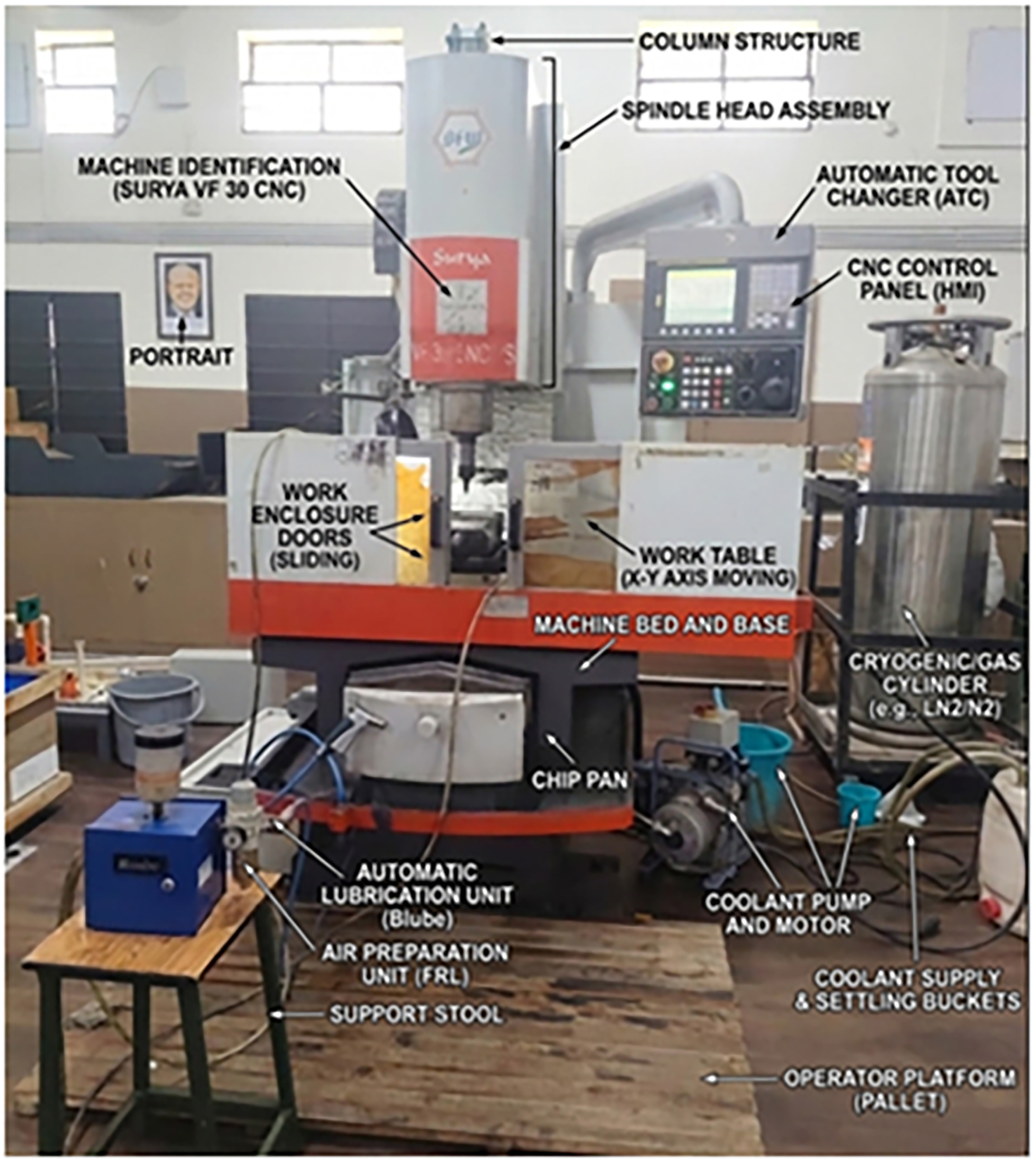
The consumption of electrical energy was monitored by using a digital power meter (Yokogawa WT310). This instrument captures voltage, current and power signals in real-time with a resolution of ±0.1%. It was plugged into the CNC machine’s main power source. The whole arrangement with the CNC machining center is illustrated in Figure 1.

Figure 1 presents a CNC VERTICAL MILLING MACHINE with MQL system along with its accessories placed in a machine shop. The arrangement presents a typical, up-to-date machining environment intended to enhance cutting efficiency performance, lubrication efficiency, and sustainable environment. It appears to be a BFW Surya VF-Series CNC milling machine, commonly found in engineering labs and manufacturing facilities for complex milling, drilling and slotting operations.
The Bluebe MQL system, at the front of the unit, sits on a base and delivers a precise amount of lubricant directly in the cutting area at the cutting interface. The system combines compressed air and a minor percentage of oil to produce a neat aerosol that is directed to the cutting tool through flexible tubes. MQL reduces the amount of lubricant used as well as the coefficients of friction and cutting temperature when compared with conventional flood cooling. This conversion provides longer tool life and less impact on nature. Located on the right side of the machine, the CNC controller is the primary control for machining. It provides a screen and keypad with control buttons through which he can execute programs, change machining parameters and monitor the machining process dictated by the G-code.
A machining enclosure is vented to the outside through a mist collector that captures the lubricant droplets and coolant vapors that become aerosolized during machining. By trapping these particles and discharging fresh air into the workspace, the system contributes to a safe and clean working environment. A cylindrical coolant tank or fluid reservoir located beside the machine contains the machining fluid for use in standard cooling applications. It also has pumps and filters for the fluid to be circulated. This arrangement makes it possible to perform comparative analyses between the standard coolant systems and MQL lubrication.
The CNC vertical milling machine comprises the spindle head, worktable, and protective enclosure. The workpiece is clamped on the table and the tool is rotating at high speed. Accurate material removal is made possible by the accurate movement along X, Y and Z axes. In general, the combined configuration acts as a platform to investigate sustainable machining through the assessment of cutting performance, energy consumption, tool wear, and environmental implications in various lubrication scenarios.
The procedure of evaluating the environmental effect of CNC milling via Life Cycle Assessment (LCA) is established in the following. This technique is associated with a CNC vertical milling. It integrates machining parameters to machine operation and resource monitoring and environmental calculations. This allows the full carbon footprint of a machining procedure to be calculated in grams of CO2 equivalent (g CO2-eq).
2.3. Machining input parameters (process planning)
The procedure begins with setting the machining input parameters. This above step is essential before machining process. The parameters are cutting speed, feed rate, tool material and type of lubrication. All of these elements have a immediate impact on the machining productivity, tool wear and energy consumption. Selecting the appropriate parameters can lead to a good machining performance and minimized environmental effect.
In the experimental setup these values are input to the CNC controller of the BFW Surya VF-series vertical machining center. This controller controls the spindle speed, feed rate and axis movement based on the programmed G-code.
2.4. CNC machining operation
When the machining parameters are set, the process enters the CNC Machining phase where the machine performs the predefined operation. There are three basic modes in this stage of operation.
-
Idle or Ready State
In this mode the machine is on but is not cutting material. Although no machining is performed, the energy consumption remains for running the CNC controller, the pumps, the cooling fans, and other auxiliary systems.
-
Material Removal Stage
This is the primary machining process in which the cutting tool contacts a workpiece. The cutting tool is rotated by the spindle, and the workpiece surface is subjected to milling to remove the material. This is generally the highest energy consuming step in precipitation/hardening due to cutting forces and tool-material interaction.
-
Spindle and Axis Movement
During the machining process the axes of the machine tool move the cutting tool along the programmed path. The tool’s position relative to the workpiece is controlled by the X, Y, and Z axes, and power is necessary to drive the servo motors that provide this motion.
2.5. Lubrication and auxiliary system operation
In machine operation the system utilizes a Bluebe MQL (Minimum Quantity Lubation) Unit. This unit sprays a minimal and controlled quantity of air-oil mist to the cutting zone. The MQL technique provides excellent lubrication at a fraction of the lubricant usage of conventional flood cooling systems.
The installation features a mist collector as well. It collects the oil aerosols generated by machining, filters them and exhausts clean air into the environment. This is what makes the air safe for the operators.
2.6. Energy and lubricant data collection
Machining resource consumption data is collected by sensors and monitoring systems during or after machining. They monitor the electrical energy for such components as the spindle motor, the axis motors, and the auxiliary equipment. They also measure the consumption of lubricant to determine how much oil the MQL consumes. These values provide elementary information for environmental assessment.
According to the specifications defined in ISO 14955-1, ISO 14955-2 and ISO 14955-3, a data-driven analytical model is derived to assess the machine-tool energy consumption and the lubricant related CO2-equivalent emissions simultaneously with dry, MQL and conventional flood lubrication strategy [3–5]. The framework is based on well-established machining environmental-impact modelling principles [2] and applies IPCC-based emission conversion factors to calculate CO2-equivalent burdens, related to electricity and lubricant consumption [6]. The necessityTherefore of considering energy consumption, lubrication strategy, tool wear, and environmental indicators in machining process evaluation was also substantiated by recent sustainable machining [16, 25, 27].
2.7. Parallel environmental analysis
The data acquisition is processed in two parallel processing streams.
-
Electrical Energy Analysis
This analysis computes the electrical energy consumed by different components of the machine (i.e. spindle, axis motors, and auxiliaries such as pumps and control electronics).
-
Lubricant Impact Analysis
This analysis considers the impact on the environment associated with the use of lubricant. It takes into account the real lubricant consumption and emission factors associated with production, transport and disposal of the lubricant.
2.8. Environmental impact calculation
The energy and lubricants analysis results are consolidated to determine a certain environmental indicator. These indicators represent various portions of the overall environmental footprint:
-
IEelec.cut – amount of electricity used during cutting
-
IEelec.pump – electricity consumed by the lubrication pump
-
IEelec.axes – total energy required to perform the axis movements
-
IElub – the environmental expense related to the use of lubricant
Every factor contributes to the full environmental determinants of the machine processes.
2.9. Total environmental impact
Then all the impacts that were calculated are summed up to calculate the total environmental impact of the machining process in grams of CO2 eq (g CO2-eq). This represents the carbon footprint associated with manufacturing a particular precision machined part under the given machining conditions.
This provides the basis for evaluating the environmental efficiency of CNC machining operations. With the combination of machining parameters, machine process, energy consumption information, and lubricant analysis, this model enables scientists and engineers to identify opportunities for improved sustainability. Establishing an optimum range of cutting parameters, reducing energy consumption, and employing effective lubrication methods, such as MQL, are key routes to significantly reduce the environmental burden of the contemporary manufacturing technologies.
3. ELECTRICAL ENERGY CONSUMPTION MODELLING
3.1. Axis and spindle power at no-load
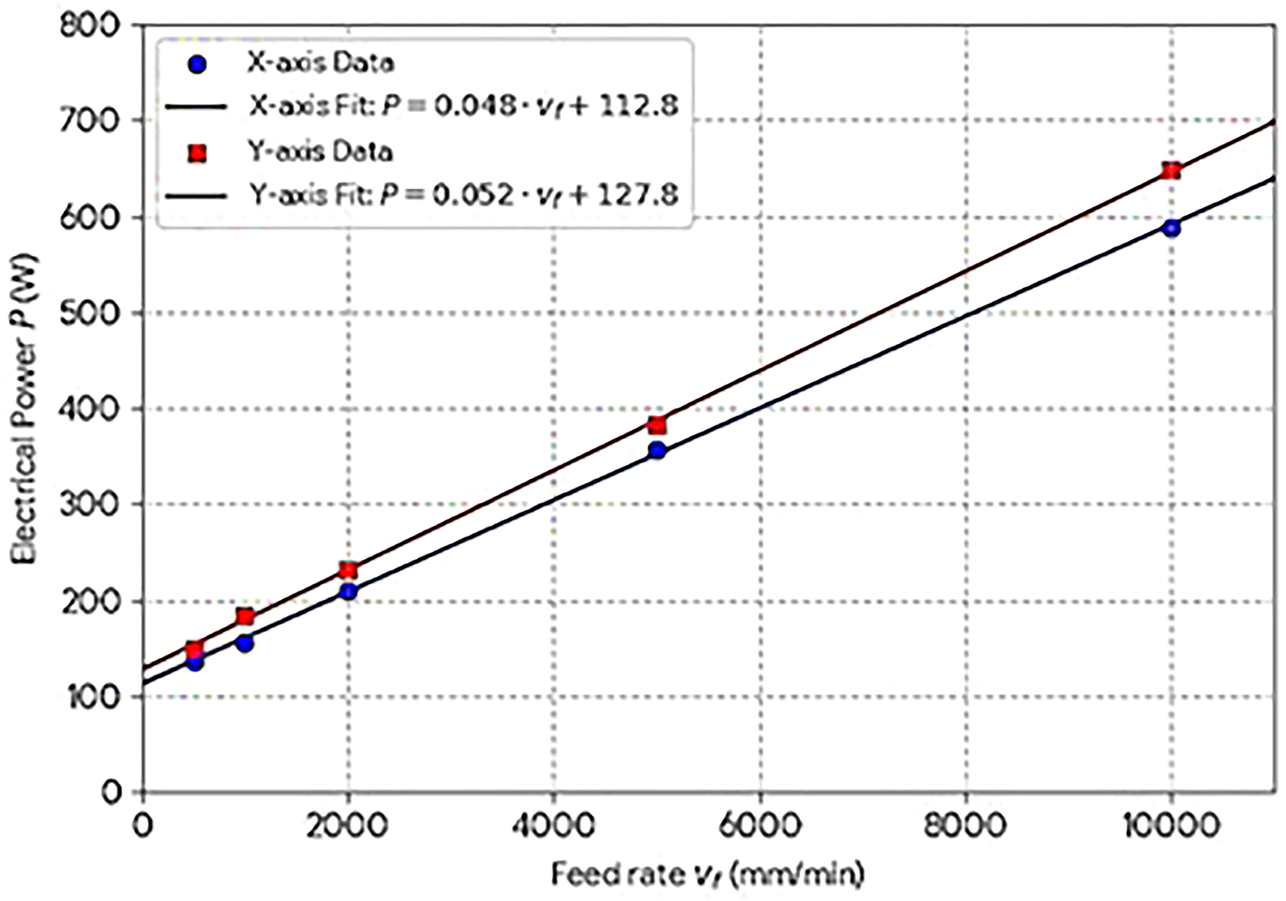
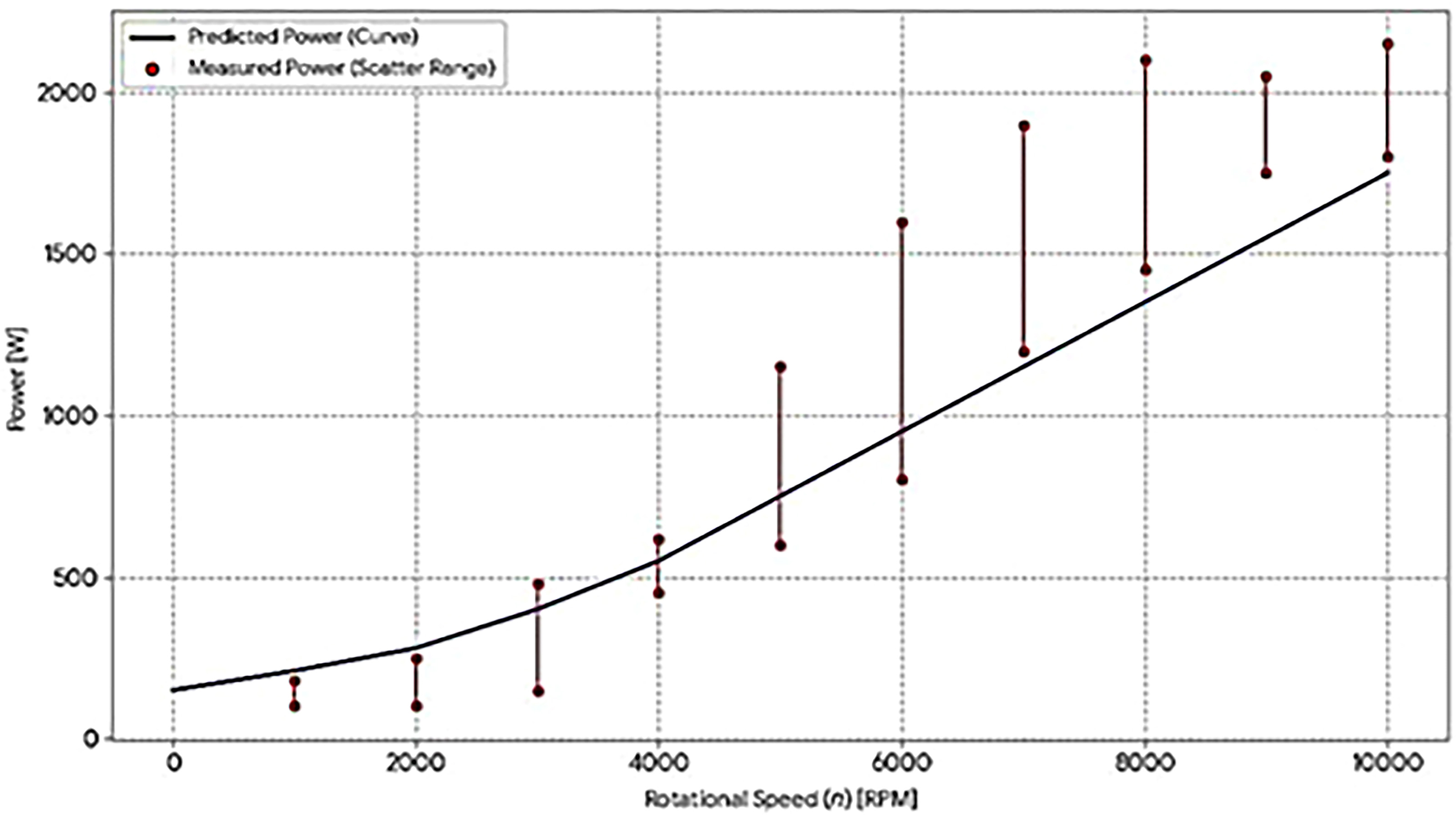
The consumption of power by the axes and spindle was experimentally determined in accordance with ISO 14955-3 procedures. The power measured was recorded against the varying axis feed rate and spindle speed. For the X and Y axes, linear regression models were obtained, whereas a speed-dependent model was established for the spindle. The average electrical power of the machine axes during no-load conditions is depicted in Figure 2. The no-load power model of the spindle as a function of the rotational speed is indicated in Figure 3.


3.2. Cutting power model
Martellotti’s milling force model serves as the foundation for deriving the mechanical cutting power, which states that the cutting forces are directly proportional to the undeformed chip’s cross-sectional area. The related electrical power is arrived at by means of a mechanical-to-electrical efficiency coefficient (Equation 2). The expression “cutting power” is from a milling equation where the chip load, or the uncut chip cross-texture area, controls the cutting forces. The elementary unit of energy and force in milling is based on Martellotti’s theory analysis of milling.
Where Pelec.cut = electrical power required for cutting (W), ηmech/elec = mechanical-to-electrical conversion efficiency, Schip = undeformed chip cross-sectional area (mm2), Kc = specific cutting force (N/mm2), Vtool/work = relative velocity between tool and workpiece (m/s).
The auxiliary system power (including pumps and compressors) was directly measured by a wattmeter, following the ISO 14955-2 recommendation.
4. ENVIRONMENTAL IMPACT MODELLING
4.1. Lubricant consumption impact
The negative environmental effect of lubricants is calculated by a carbon emission coefficient EFlub, which is 148 ± 5 g CO2-eq/L at 5% concentration and is based on the IPCC data. The losses of lubricants consist of evaporation (Noack test) and losses related to the system (8% per hour is the estimation). As per equations 3-5, three lubrication strategies are modeled. The lubricant volatility was calculated considering evaporation losses by a Noack like method. This method considers evaporation loss as mass fraction or volume fraction under an influence of heating and airflow. It is based on the standardized Noack procedure.
Conventional flood lubrication:
4.2. Effect of electrical energy
The evaluation of the environmental impact of electricity consumption is done by applying a national electricity emission factor. The influence of electricity consumption on the environment was calculated by considering the average emission factor of the Indian electricity grid. The interval represents the range of values when this factor is assumed to be 0.82 kg CO2-eq/kWh from national energy statistics. The factor is calculated as shown in Equation 6:
The general formulation is in Equation 7. The electricity-related CO2-eq is computed as the product of the measured amount of electrical energy (total power over time) and a grid emission factor. This approach is based on the inventory to impact conversion procedure used in Life Cycle Assessment (LCA) standards and national inventory methodologies.
5. EXPERIMENTAL VALIDATION
5.1. Experimental setup
A CNC machining centre fitted with a Heidenhain iTNC 530 controller was the basis for the experiments conducted. The acquisition of electrical power data was done through TNC Scope software, and the cutting forces were recorded by a Kistler 9129AA six-component dynamometer. In Table 2, the cutting parameters applied in the experiments are summarized.
5.2. Results
The model’s predictions exhibit a maximum divergence of 4% when compared to the total electrical energy that was measured. As for the total environmental impact during the tests, the figures varied from 0.74 to 1.12 g CO2-eq per operation. Figure 4 shows the measured and simulated electrical energy for the five largest machine entities during zig-zag slot milling. The results are uniformly close, both on entity and system level with deviations of a few per cent at most. This results in a maximum error of less than 4% in total energy. This demonstrates that (i) the no-load models for spindle and axes and (ii) the cutting-power conversion/processing efficiency (mech-effic) are able to represent the dominant terms involved during cutting. The breakdown reveals that the spindle no-load and cutting energy demand the greatest amount of per-operation electricity. Auxiliaries are a smaller, yet non-negligible, proportion of the total. Thus, the eco-efficiency enhancement should be oriented on: (a) the reduction of the cutting time t c without the wear increasing of the tool; (b) the increasing of the cutting efficiency via the reduction of the forces; and (c) the limiting of the auxiliary consumptions, as the pumping work, as much as possible.

Measured and simulated energy under for a zig–zag milling operation: energy consumption by machine entity. Error bars are ±1 standard deviation taken from the results of five replicates machining.
5.3. Influence of lubrication strategy
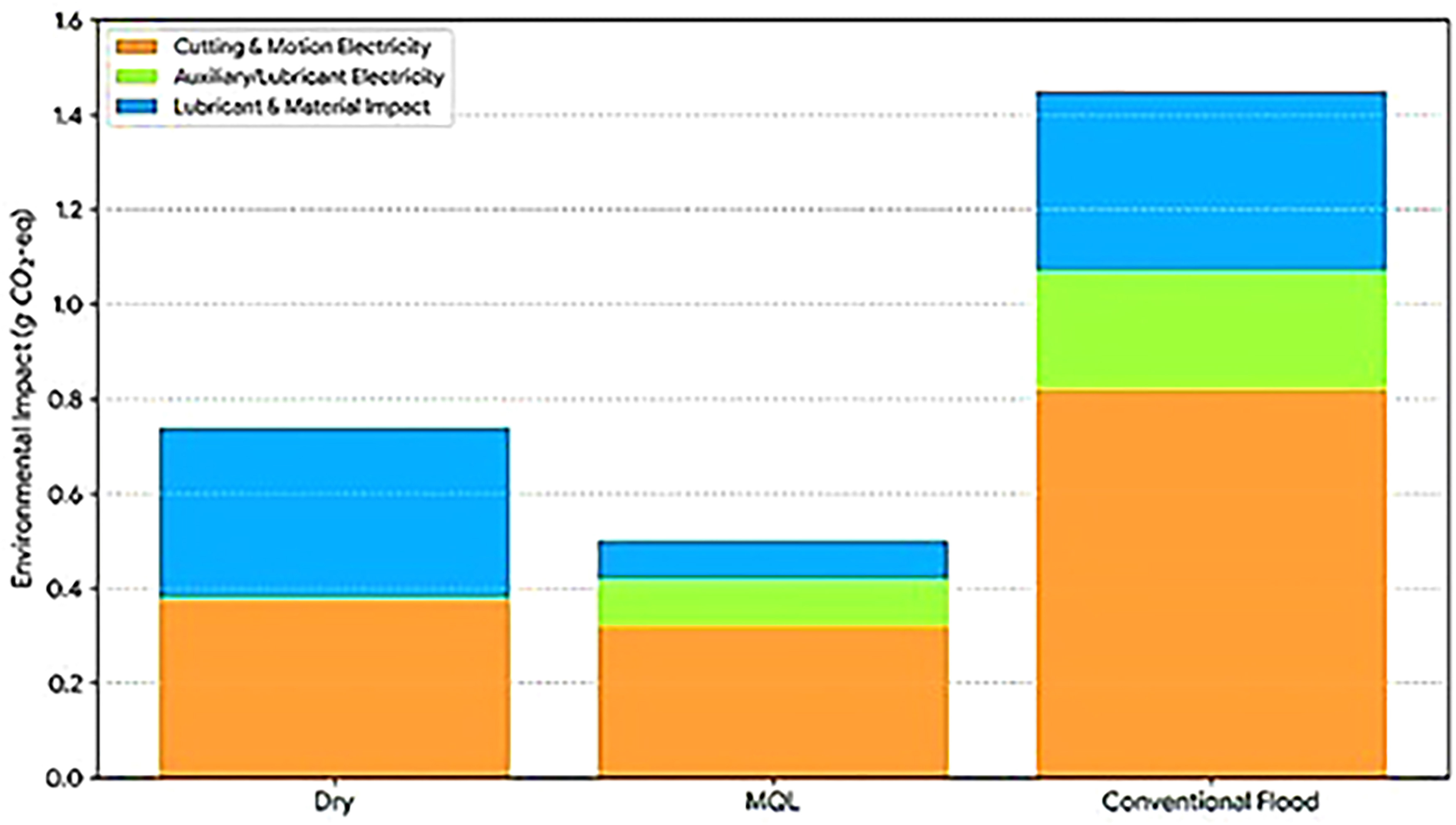
The comparative environmental-consumer impact of the lubrication techniques is represented in Figure 5. The MQL method has the least total impact because of the very low amount of consumed lubricant and a tiny lowering of cutting forces. The impact of the conventional method is very much higher because of the cost of lost lubricants and the energy consumption of the pump. Dry processing does not have any impact from lubricants but it might shorten the life of the tools and affect the reliability of the process in the case of aluminium milling.
Comparison of life cycle environmental impact (g CO2-eq) for Dry, MQL, and conventional flood lubrication strategies in milling operations.
6. ADDITIONAL ANALYSES AND EXTENDED EXPERIMENTAL VALIDATION
In order to improve the strength of the suggested environmental impact model and to test its use under real machining conditions, further analyses were carried out including tool wear, surface integrity, alternative lubrication strategies, multi-material validation, process optimization, and statistical verification among others.
6.1. Tool wear and life cycle impact assessment
The monitoring of tool wear for each lubrication strategy during the milling process of A2017 aluminum alloy was the first step in evaluating the environmental impacts related to tools. After every machining pass, optical microscopy was employed to evaluate the tool flank wear (VB). The tool life was determined as the number of slots machined until the wear criterion of VB = 0.3 mm was reached.
The highest flank wear rate was associated with dry machining, which resulted in a drop in tool life of around 25% compared to MQL, while the latter was the most favorable in this regard. The lack of lubrication during dry cutting caused an increase in both friction and heat, thus hastening the wear process on the tool; meanwhile, MQL’s provision of precise lubrication to the cutting area that came with the longest tool life among the studied methods, effectively cutting down both friction and temperature. Not only was machining performance evaluated but also the impact on the environment due to cutting tool production and disposal at the end-of-life was considered as being quite significant. The contribution was estimated to be between 0.05 g and 0.08 g CO2-eq per slot machined, which is more so when talking of scenarios where tools are replaced often, mainly in dry machining, this has been termed as “tool life”. The tool life was defined as the number of slots machined when the flankwear criterion VB = 0.3 mm was attained. This is in line with ISO tool-life testing procedures, where flank wear (VB) is the predominant wear measure in end milling evaluations. The importance of considering tool life when evaluating the environmental impact of a machining process has been brought out by these results. The wearing of tools also accounts for a proportion of the total impact and at the same time makes the case for MQL-based machining being more sustainable stronger. Tool flank wear (VB) as a function of the number of machining passes for different lubrication strategies is depicted in Figure 6. The comparison reveals the rapid wear rate caused by dry machining and also the lubricants’ contribution to lesser wear, especially under MQL that shows the least wear and the longest life of the tool. Tool wear flank was evaluated by a numerical measurement. When VB reaches 0.3 mm the tool life is finished, this is a typical value employed in studies of milling tool life. The number of machining passes is related to sequential slot milling on the X-axis in Figure 6.

Optical microscopy images of tools in wet, oil-in-water (0.5% oil concentration) and oil-in-water with nanoparticles (1% oil concentration) lubrication were investigated in Figure 7. There is excessive adhesion and BUE formation in dry cutting environment. Conversely, the adhesion is significantly reduced in the MQL condition since the tool–chip interface is better lubricated.

The SEM images in Figure 7 vividly displays the contrasts in the tool wear progression under three different lubrication conditions, dry, liquid CO2, and flood lubrication. It is occurring during the machining of aluminium alloy A2017. Tool wear and process environmental influence as a function of the tool – chip interface conditions depicted in the micrographs.
In dry cutting, the tool surface has strong adhesion and BUE (built-up edge) formation. Since the lubricating film does not exist, the rather ductile aluminum alloy adheres to the cutting edge at high temperatures and pressures. This adhesion leads to an unstable BUE that is removed from the cutting edge in an intermittent manner, carrying away small particles of tool material. Such adhesion and fracture cycles increase the rate of flank wear and this is the reason that dry cutting attains the flank wear criterion of 𝑉𝐵 = 0.3 mm approximately 25% faster than MQL. In contrast, a much cleaner tool–chip interface is preserved in the environment of MQL. Lubricant droplets of atomized form create a thin and the effective film of lubricant in the cutting zone. This decreases the friction and limits the temperature increase at the interface. That, in turn, hinders the severe adhesion and gives very thin transfer layers on the tool surface. Compared with the studied lubricating methods, this leads the smallest increase of the flank wear and the longest tool life. The dry sliding condition demonstrates the severe wear pbehavior. Despite the fact that the coolant in large amount can carry the heat away from the work zone efficiently, it might not always penetrate into the high-pressure stagnation zone at the tip of the tool as the focused MQL spray does. Hence, slight adhesion and material accumulation are still able to take place, although in a far less intense manner than what is experienced in the absence of any protective environment. On the whole, the ENV assay results support the microscopic observations. Greater tool wear during dry machining means tools are replaced more often, contributing to more tool-related CO2-eq emissions—approximately 0.08 g CO2-eq per slot. By contrast, the enhanced MQL conditions allows for more tool life and more machining passes to distribute the environmental cost of tool production. This confirms the fact that MQL results in the most environment-friendly machining condition over the considered strategy.
6.2. Surface quality assessment
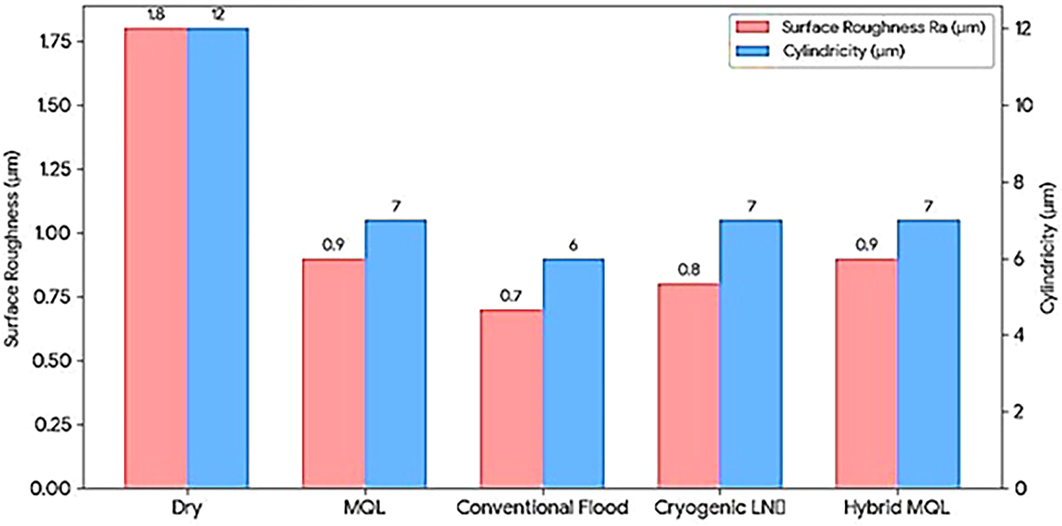
The surface analysis of integrity in Table 3 and Figure 8 indicates that the lubrication medium has a significant impact on the surface quality in the milling process. Conventional flood lubrication achieved the minimum surface roughness (Ra = 0.7 µm) and cylindricity deviation (6 µm) among the tested conditions. Such enhancement is attributed to the effective cooling/lubrication and high heat capacity of the large quantity of coolant, which reduce friction and stabilize chip formation at the tool/workpiece interface.

The MQL environment presented slightly increased values of roughness (Ra = 0.9 µm) and cylindricity deviation (7 µm) with respect to flood lubrication, but (all data) these values are all in a similar range and give a good surface quality of the aluminium milling. The improved performance on MQL is attributed to the presence of a thin lubricating film which is supplied directly to the cutting zone and reduces the friction and adhesion between the chip and tool. Similar results were reported from previous studies where MQL environments produced surface quality close to feed lubrication with a dramatic reduction in lubricant use and environmental risk.
Conversely, dry machining results in the greatest surface roughness (Ra = 1.8 µm) and cylindricity error (12 µm). It was attributed to friction increase, temperature rise and chip formation instability at the cutting interface. Adhesion and BUE formation takes place in the absence of lubricant which is detrimental to the surface finish and dimensional accuracy.
Good surface quality can be achieved in flood lubrication. Nevertheless, MQL conditions are in better between surface integrity and environmental-friendly (Eco-friendly) with regards to â-aluminum milling processes.
Similar results have been reported in previous studies. In these cases, surface roughness under MQL conditions was comparable to that under flood lubrication. While reducing cutting fluid consumption and its impact on the environment significantly [16, 18, 19].
6.3. Measurement protocol
The values for surface roughness (Ra) was obtained by using a contact stylus profilometer. The evaluation complied with ISO standards concerning profile measurement, processing, and assessment, such as sampling length, choice of cut-off, filtering, and comparison rules. The Ra is the average deviation of the evaluated profile according to the ISO profile parameter standards.
The cylindricity error was assessed as a geometrical form error according to the ISO GPA definitions. The tolerance zone consists of two coaxial cylinders. The cylindricity tolerance is the smallest radial distance between two cylinders that can contain the measured surface. In practice this is done from multiple axial traces or CMM scans over the full 360° around and along the length of the machined feature and then evaluated using the best fit associated cylinder.
6.4. Extended lubrication scenarios
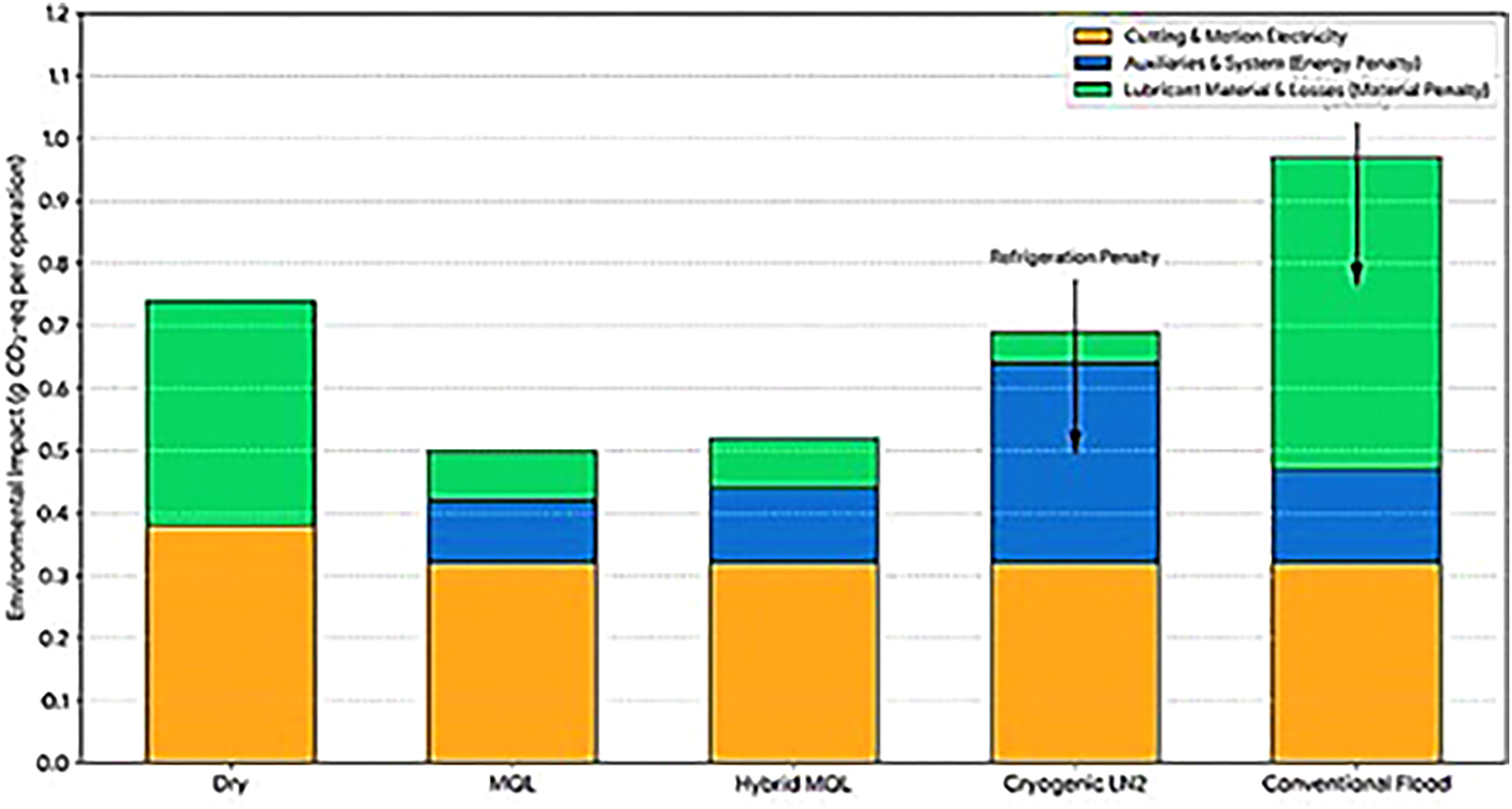
The purpose of these additional experiments was to effectively increase the scope of the analysis, and to that effect, they were performed using cryogenic LN2 cooling and a hybrid between MQL and CA (compressed air) with minimal coolant. The simulated-life lubricant regimens extend-life environmental performance assessment reveals the lubrication options are quite distinct. Total impact was smallest for dry machining (0.52 g CO2-eq) because dry manufacturing lacked any lubricant related emission contribution. MQL had a marginally greater total impact of 0.59g CO2-eq mainly because of negligible 0.03 g CO2-eq of lubricant contribution and 0.56 g CO2-eq from the electrical energy consumption. The greatest total impact was found for conventional flood lubrication with 1.10 g CO2-eq in which the only contribution of 0.50 g CO2-eq from the lubricant consumption was the most environmentally detrimental case. Cryogenic LN2 cooling had an impact of 0.70 g CO2-eq which was determined solely by the electrical use, meanwhile hybrid MQL had a moderately low total impact of 0.60 g CO2-eq with minimal emissions related to lubricant. In conclusion, MQL and hybrid MQL led to a superior compromise between machining aid and environmental sustainability as compared to traditional flood lubrication.
The data presented in Table 4 indicate that cryogenic cooling has a significant positive effect on the reduction of lubricant-related emissions, but at the same time, it increases the consumption of electrical energy, as refrigeration is necessary. On the other hand, the use of hybrid MQL, which is a method that combines very low lubricant supply and compressed air, gets a slight as total environmental impact reduction when compared to conventional MQL and, at the same time, cutting performance is similar. This is an evidence that hybrid MQL can be an eco-efficient alternative, as it, by its nature, assists energy consumption, lubricant usage, and machining functionality to be in good terms with each other.
The environmental impact components distribution for new lubrication methods is depicted in Figure 9, which also shows the amount of electrical energy consumption and lubricant-related emissions for dry machining, MQL, conventional flood, cryogenic, and hybrid MQL methods contributed relatively.

6.5. Process optimization using DOE
A Design of Experiments (DOE) method was utilized to discover the conditions that would lead to the least total environmental impact by altering the cutting speed (Vc), feed per tooth (fz), and axial depth of cut (ap) parameters as in Table 4.
The study of process optimization shows that the best eco-efficiency is realized at moderate speeds and feed rates, which constitute the best compromise among electrical energy, tool wear, and lubricant consumption. On the other hand, extremely high feed rates can reduce machining time, but they also increase the wear of the tool which is the environmental impact related to the tool’s production and replacement. Low feed rates, on the other hand, result in a longer machining time and hence higher total electrical energy consumption. The results of this study have underlined the need for selecting intermediate cutting parameters for the milling operations to minimize their overall environmental footprint.
A response surface in Figure 10 displays the total environmental impact as a function of cutting speed and feed per tooth and revealed the way in which machining parameters are affecting the three aspects of energy consumption, tool wear, and lubricant-related emissions of total environmental impact.

Response surface showing total environmental impact as a function of cutting speed and feed rate.
6.6. Statistical validation
Although the influence of lubrication strategy on environmental burden and machining quality was demonstrated in the previous sections, its confirmation through statistical analysis is necessary to confirm that the differences among lubrication environments are significant. This analysis applied ANOVA to the experimental data collected through the recurrent machining test.
The test allows us to determine if the mean of environmental impact associated to lubrication strategies is significantly different. This is a technique frequently used in machining literature to verify the results are consistent and can be repeated. The results indicated that the severity of the environmental impact of the milling operation varied considerably among lubrication techniques (p < 0.01). This confirms that the observed differences in dry machining, MQL and flood lubrication does not appear to be pure chance, but is likely to reflect true effects of process.
The results of the statistical analysis of the experimental data indicate that the differences in environmental impact among the assessed lubrication strategies are highly significant from a statistical point of view (p < 0.01). This means that the benefits of MQL compared to dry and conventional flood machining are not simply due to randomness, but are reproducible and strong enough to support the claim of MQL being the most environmentally friendly lubrication method for aluminum milling under the conditions tested. The ANOVA results for different lubrication strategies are given in Figure 11, which also shows that there have been significant differences (p < 0.01) in the environmental impact, thus confirming the reliability and strength of the experimental results.

The summary of variances for the contribution analysis indicates that the lubrication strategies explains 95.5% of the total variance in CO2-eq impact. This result implies that the observed ranking (MQL < dry < flood for total impact in the tested period) is indeed caused by the actual strategies rather than experimental noise. The high contribution rate of lubrication strategy in the ANOVA results also implies that selection of cutting environment is the dominating factor affecting the environmental performance of the milling operation.
6.7. Sensitivity analysis
A sensitivity analysis was carried out for the purpose of determining the effect of the primary model parameters on the total environmental impact, wherein the lubricant CO2 emission factor, mechanical-to-electrical efficiency, and lubricant evaporating and losing coefficients were the ones considered. The results show that the lubricant CO2 emission factor has the largest influence for the case of conventional flood cooling, while the mechanical-to-electrical efficiency has a strong impact on all lubrication strategies. The evaporation and loss coefficients have a minor impact, especially on the cases of MQL and conventional lubrication, thus underlining the need for maximizing lubricant efficiency and minimizing losses to reduce the environmental footprint.
The Figure 12 shows the values of the sensitivity indices of the key model parameters, which indicate the relative impacts of the lubricant CO2 emission factor, the mechanical-to-electrical efficiency, and the lubricant loss coefficients on the total CO2-equivalent emissions.

6.8. Comprehensive life cycle assessment (LCA)
Simplified life cycle assessment was performed according to the conventional LCA stages: goal and scope definition, inventory analysis, impact assessment, and interpretation. The functional unit is one full slot milling process for each lubrication method. The system boundary considered (i) the electricity consumption in the machining process including spindle, axes, cutting and auxiliaries (ii) the lubricant production, application and loss in the operation and (iii) a fraction of the cutting-tool fabrication and its end-of-life related to the tool life.
The energy related impact was calculated as the energy use per operation (Wh) multiplied by the grid emission factor Kelec = g CO2 – eq /Wh. The lubricant influence was calculated as the lubricant consumed and lost (through evaporation and loss in the system) multiplied by the lubricant emission factor Klib. The evaporation loss simulation included a Noack-type evaluation consistent with the conventional evaporation loss simulations.
The share of tool impact was assigned by amortizing the per tool production and end-of-life CO2-eq impact over the number of slots that can be fabricated before exceeding the wear threshold (VB = 0.3 mm), according to Equation 8.
Flank-wear-based tool-life testing and wear measurement are in the end milling case in compliance with the ISO tool-life testing guidelines.
Figure 13 displays the joint impact of electricity, lubricant and tool usage by each operation. MQL procedure is that it decrease cut total CO2-eq mainly by decreasing the use of lubricant. This also impacts tool life and the tool contribution is less. Residents of flood-affected areas typically report incomeg/livestock earning and tool contribution account for a 38% decline in total CO2-eq per operation within the study period while producing surface integrity comparable to that of near-flooded condition.

MQL has always been the lubrication method that gives the best overall performance in terms of energy use, tool life, surface quality, and environmental impact over the whole life cycle. Dry machining, on the other hand, can eliminate all emissions related to lubricants, but it still causes the tool to wear faster and the part to be of lower quality. Conventional flood lubrication emits the most impact on the environment as a total due to the use of the lubricant, losses, and the energy consumed by the auxiliary operation. The strength and applicability of the environmental impact model put forward are more firmly established by the use of multi-material validation, design of experiments (DOE) optimization, and statistical analysis.
6.9. Comparative environmental and machining performance of lubrication strategies in aluminium milling
The study has shown that the choice of lubrication method has a major effect on the energy used, the wear of tools, the quality of the surface and the environmental impact of milling aluminium. Conventional flood lubrication is the worst in terms of CO2-equivalent emissions because it involves the largest amount of lubricant and the most energy for the pump. On the other hand, dry cutting has no emissions from lubricants but the tool has a noticeably shorter life and the surface quality is worse. On the other hand, MQL continually keeps providing a good combination of advantages and disadvantages; it produces the least lubricant emissions, cutting forces are reduced, and the tool lasts longer. Cryogenic cooling and other lengthy techniques reduce the impact of the lubricant but the demand for electric energy goes up. In comparison, hybrid MQL keeps the total environmental impact low and comparable to that of conventional MQL. The assessment of surface quality shows that MQL gives a good result in both roughness and dimensional accuracy, thus, it is better than dry machining and gets close to flood lubrication in quality. Multi-material testing on Aluminium A2017, Aluminium 6061, and Titanium Ti-6Al-4V confirms that MQL is the most environmentally friendly strategy due to its robustness. Based on the guidelines from the DOE, it is recommended that for levels eco efficiency cutting speed and feed percautionary are set as moderate levels, whereas results of statistical and sensibility analyses confirm that the multivariate analysis is reproducible and the parameters related to lubricant and mechanical-to-electrical efficiency are the main contributors to the total environmental impact..In sum, MQL leads to a total of about 45% less CO2-equivalent emissions compared to conventional flood lubrication, thus it is recognized as the most sustainable aluminium milling lubrication strategy. Differences in the environmental impact coming from different lubrication modes during aluminum milling have been analyzed in Figure 14 and Figure 15. The study measured the impacts of electrical energy consumption and lubricant-related emissions, allowing to see at once the eco-efficient strategies under the specified conditions.


Comprehensive performance and environmental impact summary of different machining lubrication strategies.
In this study, aluminium alloy A2017 (Al–Cu–Mg) was selected as the workpiece material since it is a typical alloy for structural and precision parts. It is a high-machinability grade of aluminium alloys, in which adhesion, BUE formation and surface integrity are significantly influenced by lubrication strategy. The 10 mm, 3-flute WC–Co end mill with the high helix angle of 38° was used due to that it is a common industrial design which is used for aluminium slot milling. This profile is good for stable chip removal and for uniform comparison between lubrication methods. A 5% water-based emulsion was selected for flood cooling, as it is aligned with typical shop floor practice and provides a realistic baseline with respect to matters of pump energy and fluid loss. We determined lubricant evaporation losses following a Noack- type volatility assumption that complies to standardized volatility testing. This helps to ensure that fluid-loss emissions are not inadvertently underreported.
The research reinforces the idea that lubrication technique is a major factor for the selection of the machining process while considering the quality of tool life, and CO2 emissions. Conventional flood lubrication, even though it has an impact on surface and dimensional accuracy, still comes out as the worst option with the highest CO2-emissions equivalent mainly brought about by high lubricant consumption and pump energy, and this corroborates the results of PENIDO and SILVEIRA [8], who stated that fluid nature of machining increases the environmental impact very much. On the other hand, dry machining does not contribute any emissions from the used lubricant but, as noted by RATHOD et al. [9] and WANG et al. [10], the higher replacement rate and heating issue turn their lives and quality negatively. The Minimum quantity lubricating (MQL) gives the most eco-efficient option, extremely low lubricant, cutting forces are reduced and tool life get prolonged; this is in line with the findings of KUMAR et al. [18] and ZHANG and CAO [19] that recognized MQL and atomized lubrication as sustainable alternatives. Taking into account the hybrid methods that combine cryogenic LN2 cooling and hybrid MQL, these yield intermediate benefits; cryogenic cooling indeed lowers the impact of the lubricant but it comes with the drawback of higher electrical consumption, hence this coincides with VELAN et al. [17] in their discussion about energy trade-offs in cooling for higher performance. Studies around biodegradable and nano-lubricants [13,14,15, 21] provide more evidence for the good environmental and tribological effects of selective lubrication strategies, thus affirming the result that eco-efficient lubrication demands the combination of energy, tool wear, and emissions. The process of multi-material validation and the use of design of experiments (DOE) for optimization have proven that MQL is the best strategy for both aluminium and titanium alloys. The findings are in line with the idea of energy-lubrication modeling suggested by PIMENOV et al. [16] and CAO et al. [20]. To sum up, the findings let us consider MQL a sustainable choice for aluminium milling with nearly 45% less total CO2-equivalent emissions than conventional flood lubrication.
7. CONCLUSIONS
In this context we developed and applied an ISO 14955-based methodology to evaluate the environmental impact in milling operation. It took into account electrical energy consumption, emissions of lubricants, and influence of tool life.Based on the experimental and analytical results the following conclusions can be drawn:
-
The environmental impact model for the proposed process predicted the electrical energy consumption of the milling process with an error below 4% in the worst case. This confirms the accuracy of the modelling methodology.
-
Depending on the used lubrication strategy, the milling process’s overall environmental burden was between 0.74 g and 1.12 g CO2-equivalent per slot.
-
Conventional flood lubrication resulted in the greatest environmental burden. This was becauseof high consumption of the lubricant and higher energy use by the coolant pumping system.
-
Dry machining eliminated emissions associated with tool lubricants, but resulted in increased tool wear and inferior surface finish. This resulted in an increased tool replacement and a decreased tool life.
-
Machining performance and environmental sustainability could best be balanced by MQL. It drastically decreased the use of lubricants,while maintaining good conditions in the tool-chip interface.
-
The life cycle impact results of MQL on combined tool wear and lubricant losses suggested a relative reduction of about 45% in total CO2-equivalent emissions with MQL as compared to that with conventional flood lubrication.
-
Surface integrity results showed that flood lubrication produced the lowest roughness values (Ra ≈ 0.7 µm), whereas similar quality surfaces (Ra ≈ 0.9 µm) as MQL were obtained with a significantly smaller environmental burden.
-
The statistical analysis revealed a significant influence of the lubrication strategy on the environmental impact (p < 0.01), meaning that the above observed differences between the machining environments have a statistical backing.
Therefore, in general, the suggested scheme can be considered as a valid decision aid for sustainable process planning in machining. It enables the manufacturer to decide on the lubrication strategies that mitigate environmental impact while ensuring performance in machining.
8. ACKNOWLEDGMENTS
The authors express gratitude to their university, laboratory for providing necessary facilities, datasets, and resource access.
9.DATA AVAILABILITY
The entire dataset supporting the results of this study was published in the article itself.
10. BIBLIOGRAPHY
-
[1] BYRNE, G., SCHOLTA, E., “Environmentally clean machining processes—A strategic approach”, CIRP Annals – Manufacturing Technology, v. 42, n. 1, pp. 471–474. doi: https://doi.org/10.1016/S0007-8506(07)62488-3.
» https://doi.org/10.1016/S0007-8506(07)62488-3 -
[2] MUNOZ, A.A.; SHENG, P., “An analytical approach for determining the environmental impact of machining processes”, Journal of Materials Processing Technology, v. 53, n. 3-4, pp. 736–758, 1995. doi: https://doi.org/10.1016/0924-0136(94)01764-R.
» https://doi.org/10.1016/0924-0136(94)01764-R - [3] INTERNATIONAL ORGANIZATION FOR STANDARDIZATION, Machine tools — Environmental Evaluation of Machine Tools, ISO 14955-1, Geneva, ISO, 2017.
- [4] INTERNATIONAL ORGANIZATION FOR STANDARDIZATION, Machine tools — Environmental Evaluation of Machine Tools — Part 2: Methods for Measuring Energy Supplied to Machine Tools and Their Components, ISO 14955-2, Geneva, ISO, 2018.
- [5] INTERNATIONAL ORGANIZATION FOR STANDARDIZATION, Machine Tools — Environmental Evaluation of Machine Tools — Part 3: Energy Efficiency of Machine Tools, ISO 14955-3, Geneva, ISO, 2020.
- [6] INTERGOVERNMENTAL PANEL ON CLIMATE CHANGE, 2006 IPCC guidelines for national greenhouse gas inventories, Japan, Institute for Global Environmental Strategies, 2006.
-
[7] CAMPATELLI, G., SCIPPA, A., “Environmental impact reduction for a turning process”, Procedia CIRP, v. 55, pp. 200–205, 2016. doi: https://doi.org/10.1016/j.procir.2016.08.020.
» https://doi.org/10.1016/j.procir.2016.08.020 -
[8] PENIDO, M.V., SILVEIRA, J.L.L., “Sustainable machining energy optimization considering cutting fluid and residues recycling”, Journal of Mechanical Science and Technology, v. 39, n. 11, pp. 6947–6957, 2025. doi: https://doi.org/10.1007/s12206-025-1037-0.
» https://doi.org/10.1007/s12206-025-1037-0 -
[9] RATHOD, N.J., CHOPRA, M.K., VIDHATE, U.S., et al., “Investigation on the turning process parameters for tool life and production time using Taguchi analysis”, Materials Today: Proceedings, v. 4, pp. 5830–5835, 2021. doi: https://doi.org/10.1016/j.matpr.2021.04.199.
» https://doi.org/10.1016/j.matpr.2021.04.199 -
[10] WANG, Q., JIN, Z., ZHAO, Y., et al., “A comparative study on tool life and wear of uncoated and coated cutting tools in turning of tungsten heavy alloys”, Wear, v. 482, pp. 203929, 2021. doi: https://doi.org/10.1016/j.wear.2021.203929.
» https://doi.org/10.1016/j.wear.2021.203929 -
[11] BAGGA, P.J., BAJAJ, K.S., MAKHESANA, M.A., et al., “An online tool life prediction system for CNC turning using computer vision techniques”, Materials Today: Proceedings, v. 62, pp. 2689–2693, 2022. doi: https://doi.org/10.1016/j.matpr.2021.11.482.
» https://doi.org/10.1016/j.matpr.2021.11.482 -
[12] SIDIQ, P., ABDALRAHMAN, R.M., ROSTAM, S., “Optimizing the simultaneous cutting-edge angles, included angle and nose radius for low cutting force in turning polyamide PA66”, Results in Materials, v. 7, pp. 10, 2020. doi: https://doi.org/10.1016/j.rinma.2020.100100.
» https://doi.org/10.1016/j.rinma.2020.100100 -
[13] AWALE, A.S., CHAUDHARI, A., KUMAR, A., et al., “Synergistic impact of eco-friendly nano-lubricants on the grindability of AISI H13 tool steel: a study towards clean manufacturing”, Journal of Cleaner Production, v. 364, pp. 1, 2022. doi: https://doi.org/10.1016/j.jclepro.2022.132686.
» https://doi.org/10.1016/j.jclepro.2022.132686 -
[14] MAKHESANA, M.A., PATEL, K.M., KHANNA, N., “Analysis of vegetable oil-based nano-lubricant technique for improving machinability of Inconel 690”, Journal of Manufacturing Processes, v. 77, pp. 708–721, 2022. doi: https://doi.org/10.1016/j.jmapro.2022.03.060.
» https://doi.org/10.1016/j.jmapro.2022.03.060 -
[15] MANIKANTA, J.E., RAJU, B.N., PRASAD, C., et al., “Machining performance on SS304 using nontoxic, biodegradable vegetable-based cutting fluids”, Chemical Data Collections, v. 42, pp. 100961, 2022. doi: https://doi.org/10.1016/j.cdc.2022.100961.
» https://doi.org/10.1016/j.cdc.2022.100961 -
[16] PIMENOV, D.Y., MIA, M., GUPTA, M.K., et al., “Resource saving by optimization and machining environments for sustainable manufacturing: a review and future prospects”, Renewable & Sustainable Energy Reviews, v. 166, pp. 112660, 2022. doi: https://doi.org/10.1016/j.rser.2022.112660.
» https://doi.org/10.1016/j.rser.2022.112660 -
[17] VELAN, M.V.G., SHREE, M.S., MUTHUSWAMY, P., “Effect of cutting parameters and high-pressure coolant on forces, surface roughness and tool life in turning AISI 1045 steel”, Materials Today: Proceedings, v. 43, pp. 482–489, 2021. doi: https://doi.org/10.1016/j.matpr.2020.12.020.
» https://doi.org/10.1016/j.matpr.2020.12.020 -
[18] KUMAR, A., SHARMA, A.K., KATIYAR, J.K., “State-of-the-art in sustainable machining of different materials using nano minimum quantity lubrication (NMQL)”, Lubricants (Basel, Switzerland), v. 11, n. 2, pp. 64, 2023. doi: https://doi.org/10.3390/lubricants11020064.
» https://doi.org/10.3390/lubricants11020064 -
[19] ZHANG, W., CAO, T., “Cutting performance of a tool with continuous lubrication of atomized cutting fluid at the tool–chip interface”, International Journal of Advanced Manufacturing Technology, v. 126, n. 1-2, pp. 117–130, 2023. doi: https://doi.org/10.1007/s00170-023-11116-7.
» https://doi.org/10.1007/s00170-023-11116-7 -
[20] CAO, T., LI, Z., ZHANG, S., et al., “Cutting performance and lubrication mechanism of micro-textured tool with continuous lubrication on tool–chip interface”, International Journal of Advanced Manufacturing Technology, v. 125, n. 3-4, pp. 1815–1826, 2023. doi: https://doi.org/10.1007/s00170-023-10821-7.
» https://doi.org/10.1007/s00170-023-10821-7 -
[21] RAJU, R.S.U., SATYANARAYANA, G., PRAKASH, M.A., et al., “Wear characteristics of alternative, biodegradable cutting fluids”, Materials Today: Proceedings, v. 26, pp. 1352–1355, 2020. doi: https://doi.org/10.1016/j.matpr.2020.02.274.
» https://doi.org/10.1016/j.matpr.2020.02.274 -
[22] YURTKURAN, H., BOY, M., GÜNAY, M., “Investigation of machinability indicators during sustainable milling of 17-4PH stainless steel under dry and MQL environments”, Proceedings of the Institution of Mechanical Engineers, Part E: Journal of Process Mechanical Engineering, v. 239, 2023. doi: https://doi.org/10.1177/09544089231189640.
» https://doi.org/10.1177/09544089231189640 -
[23] KORKMAZ, M.E., GUPTA, M.K., ÇELİK, E., et al., “A sustainable cooling/lubrication method focusing on energy consumption and machining characteristics in high-speed turning of aluminium alloy”, Sustainable Materials and Technologies, v. 40, e00919, 2024. doi: https://doi.org/10.1016/j.susmat.2024.e00919.
» https://doi.org/10.1016/j.susmat.2024.e00919 -
[24] GÜNAY, M., KORKMAZ, M.E., “Understanding the relationship between surface quality and chip morphology under sustainable cutting environments”, Materials, v. 17, n. 8, 1826, 2024. doi: https://doi.org/10.3390/ma17081826.
» https://doi.org/10.3390/ma17081826 -
[25] YURTKURAN, H., DEMİRTAŞ, G., YAZARLI, B., et al., “Optimization of energy consumption in milling of Inconel 718 alloy and prediction model using machine learning techniques”, Manufacturing Technologies and Applications, v. 6, n. 3, pp. 296–307, 2025. doi: https://doi.org/10.52795/mateca.1792370.
» https://doi.org/10.52795/mateca.1792370 -
[26] ÇAKIROĞLU, R., GÜNAY, M., “Analysis of surface roughness and energy consumption in turning of C17500 copper alloy under different machining environments using response surface methodology”, Proceedings of the Institution of Mechanical Engineers, Part E: Journal of Process Mechanical Engineering, v. 237, n. 2, pp. 207–219, 2023. doi: https://doi.org/10.1177/09544089221101368.
» https://doi.org/10.1177/09544089221101368 -
[27] SIVALINGAM, V., ZHOU, Q., SELVAM, B., et al., “A mathematical approach for evaluating sustainability indicators in milling of aluminium hybrid composites under eco-friendly cooling strategies”, Sustainable Materials and Technologies, v. 36, e00605, 2023. doi: https://doi.org/10.1016/j.susmat.2023.e00605
» https://doi.org/10.1016/j.susmat.2023.e00605 -
[28] SOREN, T.R., KUMAR, R., PANIGRAHI, I., et al., “Machinability behavior of aluminium alloys: a brief study”, Materials Today: Proceedings, v. 18, n. 7, pp. 5069–5075, 2019. doi: https://doi.org/10.1016/j.matpr.2019.07.502.
» https://doi.org/10.1016/j.matpr.2019.07.502 -
[29] KHATAI, S., SAHOO, A.K., KUMAR, R., et al., “Contemporary advancement of intelligent machining and sustainability aspects in hard machining: a critical review”, E3S Web of Conferences, v. 430, 01296, 2023. doi: https://doi.org/10.1051/e3sconf/202343001296.
» https://doi.org/10.1051/e3sconf/202343001296 -
[30] KAR, B.C., PANDA, A., KUMAR, R., et al., “Research trends in high speed milling of metal alloys: a short review”, Materials Today: Proceedings, v. 26, n. 2, pp. 2657–2662, 2020. doi: https://doi.org/10.1016/j.matpr.2020.02.559.
» https://doi.org/10.1016/j.matpr.2020.02.559